




Check on the car
To check, you need a DC voltmeter with a scale of up to 15-30 V, accuracy class of at least 1.0.
After 15 minutes of engine operation at medium speeds with the headlights on, measure the voltage between terminal "30" and the generator housing. The voltage should be within 13.6-14.6 V.
If there is systematic undercharging or overcharging of the battery and the regulated voltage does not fall within the limits specified above, the voltage regulator must be replaced.
Checking the removed regulator
The voltage regulator, removed from the generator, is checked according to the diagram shown in Figure 131. It is better to check it assembled with the brush holder, since in this case you can immediately detect breaks in the brush terminals and poor contact between the terminals of the voltage regulator and the brush holder.
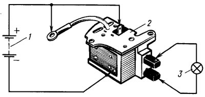
Figure 131. Circuit for testing the voltage regulator: 1 - battery; 2 - voltage regulator; 3 - control lamp
A 1-3 W, 12 V lamp is connected between the brushes. A power source with a voltage of 12 V, and then 15-16 V is connected to terminals "B", "B" and to the regulator ground. If the regulator is in good working order, then in the first case the lamp should light, and in the second case it should not.
If the lamp lights up in both cases, then there is a breakdown in the regulator, and if it does not light up in both cases, then either there is a break in the regulator or there is no contact between the brushes and the terminals of the voltage regulator.
Checking the capacitor
The capacitor serves to protect the electronic equipment of the car from voltage pulses in the ignition system, as well as to reduce interference with radio reception. Damage to the capacitor or weakening of its fastening on the generator (deterioration of contact with the body) it is detected by an increase in interference to radio reception when the engine is running.
The capacitor's condition can be approximately checked with a megohmmeter or tester (on a scale of 1-10 MOhm). If there is no break in the capacitor, then when the device probes are connected to the capacitor terminals, the arrow should move toward decreasing resistance, and then gradually return back. The capacitor's capacity is 2.2 μF ±20%.