




The shaft of the ignition distributor sensor is connected to the tail of the camshaft in only one position. Therefore, before installation, turn the shaft of the distributor sensor to such a position that the cams of the shaft coupling are opposite the grooves of the camshaft.
Place a sealing ring on the flange of the sensor-distributor. Install the sensor-distributor on the housing of the auxiliary units in such a position that the middle division on the flange of the sensor-distributor is opposite the mounting protrusion on the housing of the auxiliary units (see figure 34). Install the bracket for fastening the high-voltage wires. Secure the bracket and the distributor sensor with nuts. Connect the wires and vacuum hose to the distributor sensor, then check and, if necessary, adjust the ignition timing.
To replace any parts, disassemble in the following order. Remove cover 8 (figure 143), rotor 9 and protective screen 10. Disconnect the vacuum regulator rod 3 from the sensor support plate 6, unscrew the fastening screws and remove the vacuum regulator. Unscrew the fastening screws and remove the support plate 6 assembled with the sensor 5 and the holder 7: Remove the spring from the coupling 1, remove the pin and remove the coupling and adjusting washers from the shaft. Remove the shaft with the centrifugal regulator 4 and washers from the housing 2.
Assembly is performed in the reverse order of disassembly. When assembling, it is necessary to select adjusting washers to ensure axial free play of the shaft of no more than 0.35 mm.
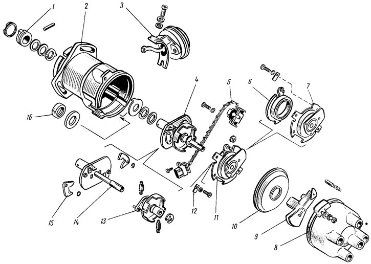
Figure 143. Distributor sensor parts: 1 - coupling; 2 - body; 3 - vacuum regulator; 4 - centrifugal regulator; 5 - contactless sensor; 6 - sensor support plate; 7 - Front sensor bearing holder; 8 - lid; 9 - rotor; 10 - protective screen; 11 - front roller bearing holder assembled with sensor support plate; 12 - wire fastening washer; 13 - driven plate of centrifugal regulator with screen; 14 - shaft with leading plate of centrifugal regulator; 15 - weights; 16 - oil seal