
English Русский
Български
Беларускі
Український
Српски
Hrvatski
Română
Polski
Slovenský
Magyar
| Articles | Contacts | Sitemap |   
Repair and maintenance Lada Repair and maintenance Mazda Repair and maintenance Mitsubishi Repair and maintenance Toyota Repair and maintenance Land Rover Repair and maintenance Hyundai Repair and maintenance Nissan
VAZbook.ru


Main     1111   2101   2105   2106   2107   2109   2110   2115   2121  
VAZ-2108 (1984-2003) VAZ-2109 (1984-1997) VAZ-21099 (1990-2004)
  • Main
  • «Sputnik»
  • VAZ-2108
  • Electrical equipment
  • Ignition system
  • Ignition coil and switch — testing on the bench

Ignition coil and switch — testing on the bench (VAZ-2108)

            0

Check the winding resistance and insulation resistance. The resistance of the primary winding at 25°C should be (0.45±0.05) Ohm, and the secondary winding (5±0.5) kOhm. The insulation resistance to ground should be at least 50 MOhm.

The switch is checked using an oscilloscope and a rectangular pulse generator according to the diagram shown in Figure 141,a, with a supply voltage of 12 V. It is advisable to use a two-channel oscilloscope. One channel is used to monitor the generator pulses, and the second for the switch pulses.
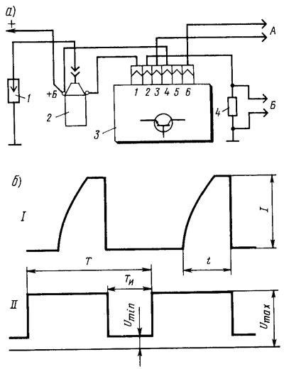
Figure 141. Circuit for testing the switch (a) and the pulse shape on the oscilloscope screen (b):…

Figure 141. Circuit for testing the switch (a) and the pulse shape on the oscilloscope screen (b): 1 - spark gap; 2 - ignition coil; 3 - switch; 4 resistor 0.01±1% Ohm, not less than 20 W, A - to the rectangular pulse generator; B - to the oscilloscope; t - current accumulation time; l - maximum current value; I - commutator pulses; II - generator pulses


When assembling a circuit to test the switch, make sure that the low-voltage wires are not in the same bundle with the high-voltage wires. In addition, it is not allowed to disconnect the plug from the switch with the ignition on (with the power supply voltage on), since in this case, voltage of up to 400 V may occur on individual elements of the switch circuit and the switch will be damaged.


Rectangular pulses with a frequency of 3.33 to 233 Hz from the generator, simulating sensor pulses, are fed to terminals "3" and "6" of the switch. The pulse duty cycle, i.e. the ratio of the period to the pulse duration, is Y/Yand=3. Maximum voltage Umax=10 V, and the minimum Umin≤0.4 V (figure 141.6). The output resistance of the generator should be 100-500 Ohms.

In a serviceable switch, the shape of the current pulses should correspond to the oscillogram I. The value of the current l should be 8-9 A, and the time t of its accumulation should be no more than 8.5 ms at a frequency of 33.3 Hz and no less than 4 ms at a pulse frequency of 150 Hz.

If the shape of the commutator pulses is distorted, then there may be interruptions in spark formation or it may occur with a delay. In this case, the engine will overheat and not develop rated power.

The article is taken from an online resource VAZBOOK.ru


This article is available at russian, bulgarian, belarusian, ukrainian, serbian, croatian, romanian, polish, slovak, hungarian
The text was reviewed by the specialist: Grigory Vologodtsev

Share with friends:

Previous articles
VAZ-2108: Ignition system
Next articles

Ignition distributor sensor — testing on the bench
Checking the ignition system elements on a car
Possible malfunctions of the ignition system
Features of the ignition system
Spark plugs — testing on the bench
Ignition Switch — Bench Test
Radio interference suppression elements — bench testing
Ignition distributor sensor — removal and installation
Ignition Switch — Removal and Installation

More articles from other manuals on VAZ cars:
➠ Ignition coil — testing on the bench VAZ-21051 (1979-2010)
➠ Testing ignition system elements on a stand VAZ-1111 (1988-1996)
➠ Ignition switch VAZ-21011 (1974-1983)
➠ Ignition switch (lock) VAZ-2106 (1976-2006)
➠ Ignition switch (lock) VAZ-2107 (1982-2012)
Link in different formats to this page


Visitor comments

No comments yet


How much will 25 + 46 ?


VAZ-21099 (1990-2004) 
  • General information
  • Specifications
  • User manual
  • Maintenance
  • Car care
  • Troubleshooting
  • Power unit
  • Engine repair
  • Cooling and lubrication system
  • Power and exhaust system
  • Transmission
  • Car gearbox
  • Clutch and drive shafts
  • Chassis
  • Car suspension
  • Steering
  • Brake system
  • Body
  • Exterior
  • Interior
  • Doors and locks
  • Electrical equipment
  • Equipment and devices
  • Lighting and signaling
  • Engine electrics
  • Ignition system


VAZ-2109 (1984-1997) 
  • General information
  • Vehicle operation
  • Vehicle device
  • Power unit
  • Engine repair
  • Cooling and lubrication system
  • Supply system
  • Transmission
  • Clutch
  • Gearbox and drive
  • Chassis
  • Car suspension
  • Steering
  • Brake system
  • Body
  • Body elements
  • Electrical equipment
  • Engine electrics
  • Equipment and devices


VAZ-2108 (1984-2003) 
  • General information
  • Introduction to guide
  • Power unit
  • Engine repair
  • Cooling and lubrication system
  • Power and exhaust system
  • Transmission
  • Clutch and drive shafts
  • Car gearbox
  • Chassis
  • Front suspension
  • Rear suspension
  • Steering
  • Brake system
  • Body
  • Exterior
  • Interior
  • Doors and glass
  • Electrical equipment
  • Equipment and devices
  • Engine electrics
  • Ignition system


VAZbook.ru © 2017 · Mobile version · Contact with administration · Sitemap: EN BG BY UA RS HR RO PL SK HU · Site search · News and articles VAZ-1111 · VAZ-11113 · VAZ-2101 · VAZ-21011 · VAZ-2104 · VAZ-2105 · VAZ-21051 · VAZ-2106 · VAZ-21061 · VAZ-2107 · VAZ-21099 · VAZ-2109 · VAZ-2108 · VAZ-2110 · VAZ-2112 · VAZ-2114 · VAZ-2115 · VAZ-2121 · VAZ-21213 · VAZ-21214 ·
The site stores technical data using cookies to improve the service.