




Contents: Disassembly ↓ Assembly ↓
Disassembly
The washed and cleaned engine is placed on a disassembly stand and the oil is drained from the crankcase.
Remove hose 1 (figure 22) and hose 2 of the engine crankcase ventilation system; remove hoses 4 and 7, respectively, for supplying and draining liquid from the cooling system to the carburetor and tube 8 for taking off vacuum to the vacuum regulator of the ignition distributor sensor. Remove carburetor 3 with spacer 5 and heat-insulating screen 6.
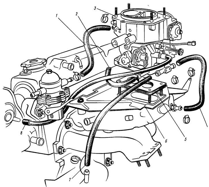
Figure 22. Disassembling the engine - removing the carburetor
Remove the high voltage wires and the ignition distributor sensor 1 (figure 23) with sealing ring 3 and bracket 2. Remove fuel pump 8 with heat-insulating spacer 6, pusher 7 and gaskets. Remove housing 4 of auxiliary units with sealing ring 5.
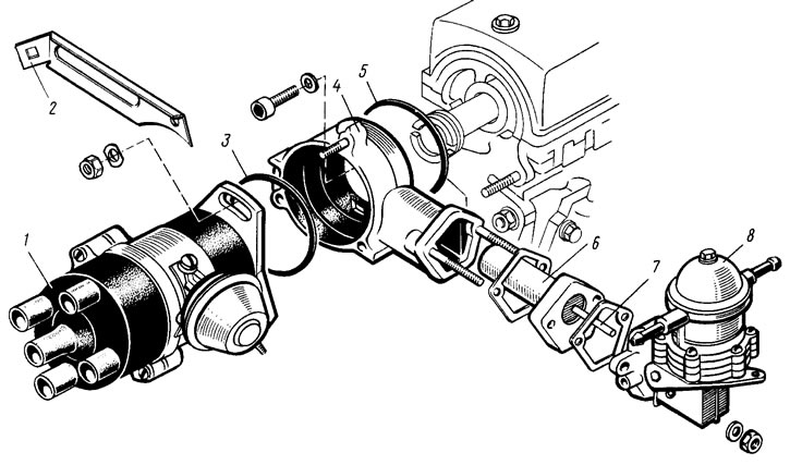
Figure 23. Disassembling the engine - removing the fuel pump and ignition distributor sensor
Remove tension bar 1 (figure 24) and the belt 4 of the generator 2 drive. Remove the generator and its mounting bracket 3. Lock the flywheel with the lock 67.7820.9526 (see figure 29), unscrew the pulley mounting bolt 5 (see figure 24) generator drive and remove the pulley.
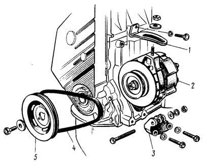
Figure 24. Disassembling the engine - removing the generator and pulley
Remove the front cover 1 (figure 25) toothed belt with rubber seal 2. Unscrew the tension mechanism fastening nut. Loosen and remove toothed belt 3. Remove tension roller 6 with axle 7 and spacer ring 5. Holding pulley 4 of the camshaft from turning with device 67.7811.9509 or another by the pulley holes, unscrew the fastening bolt and remove the pulley. Remove toothed pulley 8 from the engine crankshaft.
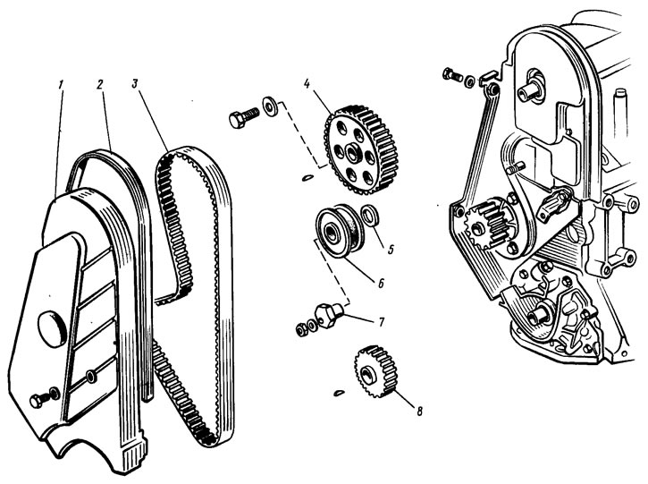
Figure 25. Disassembling the engine - removing the camshaft drive
Loosen the pump mounting bolts 2 (figure 26) coolant. Loosen the bolt and nut securing the rear cover 1 of the toothed belt and remove it.
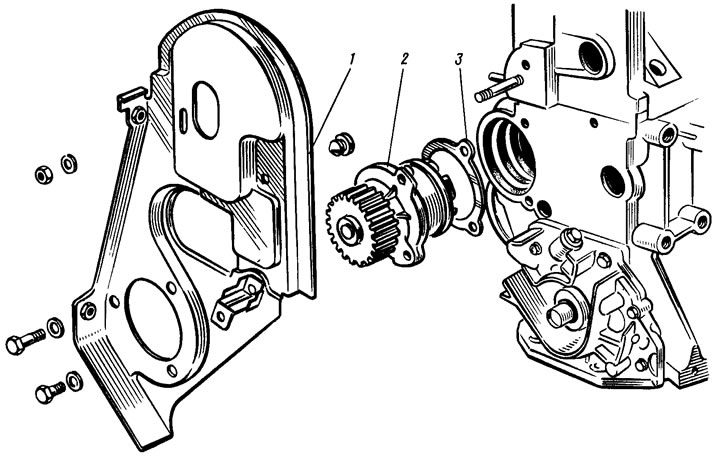
Figure 26. Disassembling the engine - removing the coolant pump
Remove the coolant pump with gasket 3 from its socket in the cylinder block.
Remove the intake and exhaust pipes with gaskets, warm air intake and coolant pump feed pipe bracket. Unscrew the oil pressure warning light sensor from the cylinder head. If complete engine disassembly is not required, the cylinder head can be removed as a complete assembly with pipes and auxiliary units.
Remove the coolant supply and outlet hoses to the heater. Disconnect the hoses from the thermostat and remove it. Remove the coolant pump supply pipe and the cooling jacket outlet pipe with the gasket. Key 67.7812.9514 (tubular end 21 mm) unscrew the coolant temperature gauge sensor and spark plugs.
With the device A.60312 (figure 27) remove the oil filter with the gasket. Disconnect the crankcase exhaust ventilation hose from the pipes on the cylinder head and block. Remove the oil level indicator.
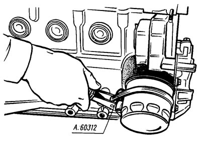
Figure 27. Removing the oil filter
Remove the cylinder head cover. Loosen the mounting bolts and remove the cylinder head together with the camshaft. If necessary, disassemble the cylinder head (see "Disassembly and assembly of the cylinder head").
Turn the engine over with the crankcase facing up and remove the oil pan 5 (figure 28) with gasket 4. Remove oil receiver 3 and oil pump 1 with gasket 2. Unscrew the nuts of the connecting rod bolts, remove the connecting rod caps and carefully remove the pistons with connecting rods through the cylinders.
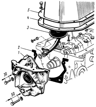
Figure 28. Disassembling the engine - removing the oil pump
Lock the flywheel with lock 67.7820.9526 (figure 29), unscrew the flywheel mounting bolts, remove the bolt washer (ring) and flywheel from the crankshaft. Remove the main bearing caps together with the lower liners. Remove the crankshaft from the bearing seats, and then the upper liners and thrust half rings from the middle support.
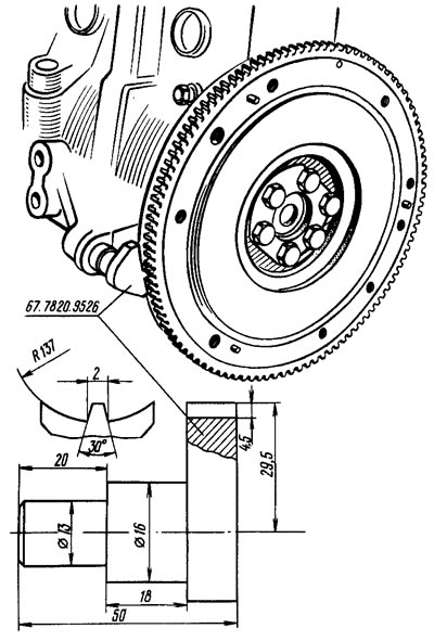
Figure 29. Locking the flywheel with a locking device
Assembly
The washed and cleaned cylinder block is installed on the stand and the missing studs are screwed in. The generator mounting bracket is installed and secured with two bolts.
Lubricate the bearing shells and the crankshaft thrust half rings, as well as the pistons and seals with engine oil. When assembling the engine after repair, install new crankshaft seals. Install the shells in the main bearing seats and caps. Place the crankshaft in the main bearings and insert the thrust half rings with grooves into the middle main bearing seats (on this side there is an antifriction layer) towards the thrust surfaces of the crankshaft.
Install the main bearing caps in accordance with the marks (figure 30). The lids must be positioned so that the marks (or the side with the most marks) were located on the generator installation side. Tighten the cover mounting bolts.
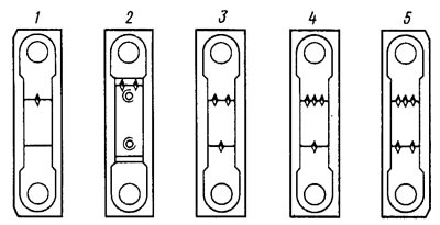
Figure 30. Marks on the main bearing caps (the number of marks corresponds to the bearing number)
Check the axial clearance of the crankshaft. To do this, turn the cylinder block with the back side up (figure 31) and install a stand with an indicator on it so that the indicator leg rests against the crankshaft flange. By moving the shaft up and down with screwdrivers like levers, measure the axial clearance with an indicator. It should be 0.06-0.26 mm. If the clearance is greater, then it is brought to normal by installing thrust half rings with a thickness increased by 0.127 mm.
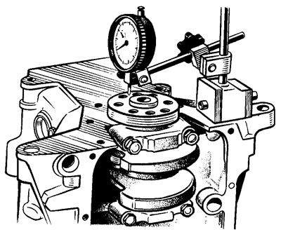
Figure 31. Checking the axial free play of the crankshaft
Using mandrel 67.7853.9571*, press the rear crankshaft oil seal into the holder. Place the holder with the oil seal on conical mandrel 67.7853.9572** and slide it from the mandrel to the crankshaft flange. Place a gasket under the holder and attach it to the cylinder block using bolts and spring washers.
* Cylindrical mandrel 0 106 mm with guide belt 0 78 mm.
** Glass with an outer diameter of 80 mm and a conical chamfer of 15°.
Install the flywheel on the crankshaft so that the mark (cone-shaped hole) near the rim was opposite the axis of the crank pin of the 4th cylinder. Install the washer and flywheel mounting bolts. Lock the flywheel with the lock 67.7820.9526 (see figure 29) and tighten the mounting bolts.
The pistons are matched to the cylinders so that the gap between the piston and the cylinder is 0.025-0.045 mm. On a new engine, this is achieved by installing pistons of the same class as the cylinders. On engines that have been in operation, the pistons and cylinders have some wear. Therefore, it is necessary to re-match the pistons to the cylinders, measuring their diameter (see the section "Device Features" in this chapter), so that the gap is as close as possible to the calculated one.
Collect pistons with connecting rods (see below "Disassembly and assembly of the connecting rod and piston group"). Using the bushing from the A.60604 kit, insert the pistons with connecting rods into the cylinders (figure 32). The kit includes bushings of normal and repair piston sizes. Therefore, it is necessary to select a bushing suitable for the given size of the piston being installed.
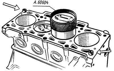
Figure 32. Installing the piston with piston rings into the cylinder using the mounting sleeve from kit A.60604. The arrows indicate the sleeves for centering the head on the cylinder block
You can also use the adjustable sleeve 67.7854.9517. The pin hole on the piston is offset by 1.2 mm, so when installing the pistons in the cylinders, the arrow on the piston bottom should point towards the camshaft drive.
Install the liners in the connecting rods and connecting rod caps. Connect the connecting rods to the crankshaft journals, install the caps and tighten the connecting rod bolts. Connecting rod caps must be installed so that the cylinder number on the cap is opposite the cylinder number on the lower connecting rod head.
Using mandrel 67.7853.9580, press the front crankshaft oil seal into the oil pump cover until it stops. Pour some engine oil into the pump and turn the drive gear several times. Insert the guide sleeve of mandrel 67.7853.9580 into the oil seal pressed into the oil pump and turn the drive gear to a position where it can be put on the crankshaft journal. Move the pump from the guide sleeve onto the shaft, install a gasket under the pump and attach it to the cylinder block.
For correct installation, two guide pins are pressed into the pump housing and must fit into the corresponding holes in the cylinder block.
Insert the oil receiver with a sealing ring into the hole of the oil pump, attach it to the oil pump and to the cover of the second main bearing of the crankshaft (see figure 28).
Install the oil pan with the gasket and secure it. Lubricate the oil filter sealing ring with engine oil and install the oil filter, manually screwing it to the fitting on the cylinder block.
Two centering bushings are inserted into the cylinder block (see figure 32) and install a new cylinder head gasket on them (it is not allowed to use a used gasket). Before installing the gasket, remove oil from the mating surfaces of the head and cylinder block. The gasket must be clean and dry. Oil must not be allowed to get on the surface of the gasket. Install the cylinder head, assembled in accordance with the instructions in Section, on the centering bushings. "Disassembly and assembly of the cylinder head".
Check the length of the cylinder head bolts (excluding bolt head). If the length of the bolts is more than 135.5 mm, they are replaced with new ones. To ensure reliable sealing and to prevent tightening of the bolts during maintenance, the cylinder head mounting bolts are tightened in a certain sequence (see figure 18) and in four doses (see section. "Removal and installation the cylinder head").
Insert the coolant pump with the gasket into the cylinder block socket, checking the reliability of the pump pulley pressing onto the shaft (see "Disassembling and assembling the coolant pump"). Install the rear cover of the timing belt and attach it together with the pump cover to the cylinder block. Additionally, attach the cover with a bolt to the cylinder block and a nut to the stud on the cylinder head.
Insert segment keys into the sockets on the front ends of the crankshaft and camshaft and install the toothed pulleys. Holding the camshaft pulley from turning with device 67.7811.9509, secure the pulley with a bolt and washer. Turn the camshaft pulley until the mark on the pulley aligns with the installation whisker on the rear protective cover of the toothed belt (see figure 6).
Turn the crankshaft to a smaller angle until the timing mark on the pulley aligns with the mark on the oil pump cover. The crankshaft can be turned with a wrench by the bolt temporarily screwed into the front end of the shaft, or by the flywheel.
Install the tension roller with the axle and spacer ring and secure it in a position corresponding to the minimum belt tension.
Put the toothed belt on the crankshaft pulley and, pulling both branches of the belt, put the left branch on the coolant pump pulley and put it behind the tension roller. Put the belt on the camshaft pulley and slightly tighten it with the tension roller, turning the roller axis counterclockwise. When installing the belt, do not allow it to bend sharply.
Turn the crankshaft two revolutions in the direction of rotation and check the alignment of the timing marks (see figure 6).
If the marks do not match, then loosen the belt tension, remove it from the camshaft pulley, turn the pulley to the required angle, put on the belt, slightly tighten it with the tension roller, turn the crankshaft again by two turns and check the alignment of the installation marks.
If the marks match, adjust the belt tension and valve clearances as specified in the "Engine Adjustments" section. Install the front toothed belt cover and secure it with bolts. Carefully place the gasket in the groove of the cylinder head cover along the entire perimeter. Install the cover on the cylinder head, put the rubber bushings on the studs and screw on the nuts and washers. If the bushings show signs of damage, replace them with new ones. Tighten the nuts evenly in several stages until the washer stops in the stud. It is important to remember that the tightness of the cover depends on the thoroughness of all installation operations.
Spark plugs, coolant temperature gauge and oil pressure warning light sensors are screwed into the cylinder head.
Install a discharge pipe 3 on the cylinder head (figure 33) cooling jacket with a gasket and secure it with two nuts. Install the gasket and attach the flange of the coolant pump supply pipe 1 to the cylinder block. Put the hoses leading to the thermostat on the branch pipe and supply pipe, install thermostat 2 and secure the hoses with clamps.
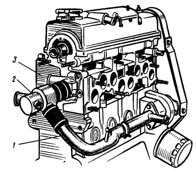
Figure 33. Installation of cooling system elements
Install the auxiliary unit housing with the sealing ring on the cylinder head and secure it with a bolt. When installing the housing, pay special attention to the position of the sealing ring in the groove, since when tightening the nuts it may jump out of the groove and get stuck between the edges of the groove and the surface of the cylinder head. If the sealing ring shows signs of being stuck, it must be replaced with a new one. Install the fuel pump with a heat-insulating spacer, with gaskets and a pusher (see section. "Removal and installation the fuel pump").
Lubricate with engine oil and place the sealing ring on the flange of the ignition distributor sensor and attach it to the auxiliary unit housing in such a position that the middle mark on the flange of the distributor sensor is opposite the mounting protrusion on the auxiliary unit housing (figure 34). At the same time, the high-voltage wire bracket is installed under the upper fastening nut. The distributor sensor shaft is connected to the camshaft tailpiece in only one position. Therefore, before installation, the shaft is turned so that the shaft coupling cams enter the grooves of the camshaft tailpiece.
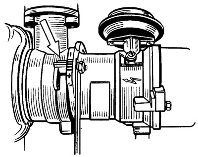
Figure 34. Installing the ignition distributor sensor. The arrow shows the mounting protrusion on the auxiliary unit housing
Place gaskets on the cylinder head studs and install the exhaust manifold 1 (figure 35) and tighten the central nut of its fastening. Then install the intake pipe 3 together with the warm air intake 4 and the bracket 2 of the coolant pump supply pipe and secure them with nuts. Install the crankcase exhaust ventilation hose and secure it with clamps on the block and cylinder head pipes. Install the oil level indicator.
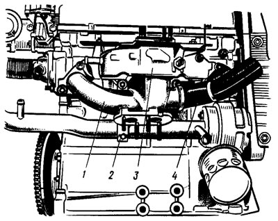
Figure 35. Installing the intake manifold and exhaust manifold
Place the generator drive pulley on the crankshaft and secure it with a bolt and washer. Install tension bar 1 (see figure 24) and generator. Place the belt on the crankshaft and generator pulleys and adjust its tension as described in Section. "Engine adjustments".
Install the carburetor heat-insulating screen, spacer and carburetor. Secure it with nuts and close it with a technological plug on top. Do not tighten the nuts or secure the heated carburetor.
Install the fuel supply hose from the fuel pump to the carburetor and secure it with clamps. Install the vacuum take-off tube to the vacuum regulator, as well as the supply and discharge hoses for the cooling system to the carburetor.
Install the hoses going to the heater on the cylinder head outlet pipe and on the coolant pump inlet pipe and secure them with clamps. Connect the high-voltage wires to the distributor sensor and spark plugs. Secure the wire comb in bracket 2 (see figure 23). Oil is poured into the engine through the filler neck on the cylinder head cover.