




Open large image in new tab »
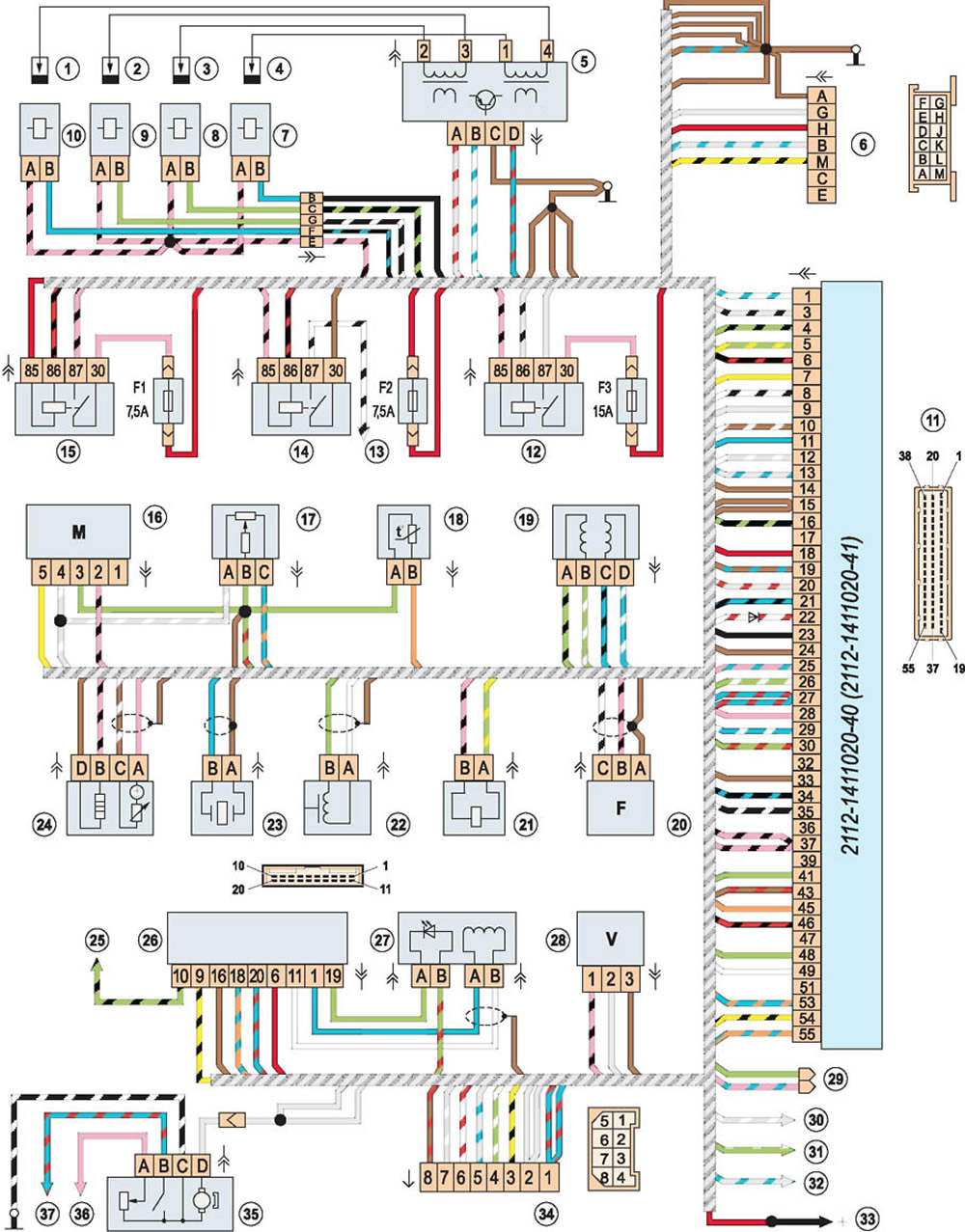
Control diagram of the injection engine 2112 (1.5i) EURO II: 1 - spark plug of the fourth cylinder; 2 - spark plug of the third cylinder; 3 - spark plug of the second cylinder; 4 - spark plug of the first cylinder; 5 - ignition module; 6 - diagnostic connector; 7 - injector of the first cylinder; 8 - injector of the second cylinder; 9 - injector of the third cylinder; 10 - fourth cylinder injector; 11 - Electronic control unit (ECU); 12 - fuel pump relay; 13 - to the engine radiator cooling fan; 14 - relay for switching on the electric fan of the engine radiator; 15 - main relay of the engine management system; 16 - MAF (mass air flow sensor); 17 - TPS (throttle position sensor); 18 - Coolant Temperature Sensor (coolant temperature sensor); 19 - IAC (idle speed control); 20 - DPDV (camshaft position sensor); 21 - purge valve of the adsorber; 22 - DPKV (crankshaft position sensor); 23 - knock sensor; 24 - oxygen concentration sensor; 25 - to the ignition switch; 26 - immobilizer control unit (APS); 27 - immobilizer sensor with alarm; 28 - speed sensor; car; 29 - spare connector (for connection to the air conditioner electrical circuit); 30 - to the oil level sensor in the engine crankcase; 31 - to the coolant temperature gauge sensor; 32 - to the engine oil pressure sensor; 33 - to the positive terminal of the battery; 34 - connector for connection to the vehicle's electrical network; 35 - fuel module; 36 - to the fuel reserve indicator lamp (on the instrument panel); 37 - to the fuel level indicator (on the instrument panel); F1 - fuse for ECU and engine management system circuits; F2 - ECU fuse; F3 - Fuel pump circuit fuse
[The text is published on the portal: VAZBOOK.ru]