




Contents: Features of the device ↓ Warnings ↓
Features of the device
The microprocessor engine management system (MEMS) is designed to control ignition (moment and energy of spark formation) and the electromagnetic valve of the carburetor forced idle economizer (EISE). The system does not require any adjustments or maintenance during operation.
The system consists of a controller 10 (figure 190) with a built-in semiconductor pressure sensor, a two-channel switch 4, ignition coils 2 and 3, spark plugs 1 and ignition switch 6, sensor 13 for starting the countdown, sensor 12 for angular pulses, sensor 11 for coolant temperature, limit switch 8 for the carburetor throttle position and electromagnetic valve 9 for the carburetor idle speed control.
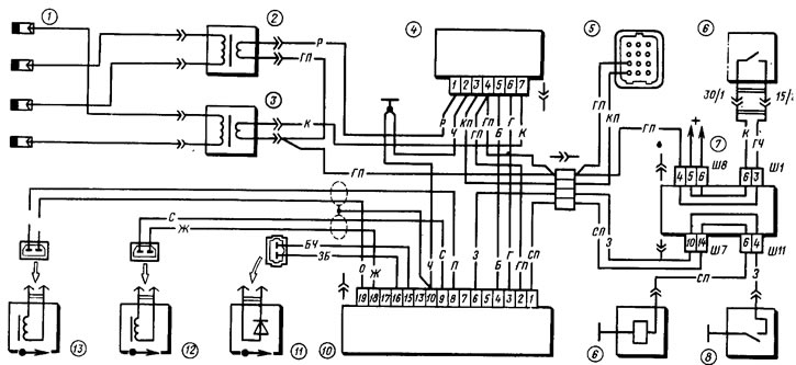
Figure 190. Schematic diagram of the microprocessor engine control system: 1 - spark plugs; 2 - ignition coil of the 2nd and 3rd cylinders; 3 - ignition coil of the 1st and 4th cylinders; 4 - switch; 5 - diagnostic block; 6 - ignition switch; 7 - mounting block; 8 - carburetor limit switch; 9 - electromagnetic valve of the carburetor idle speed control; 10 - controller; 11 - temperature sensor; 12 - angular pulse sensor; 13 - start sensor
Ignition control is carried out according to optimal characteristics depending on:
- engine crankshaft speed;
- pressure in the intake manifold;
- coolant temperature;
- carburetor throttle position.
The control of the electromagnetic valve of the idle speed control system of the carburetor is carried out depending on:
- engine crankshaft speed;
- carburetor throttle position.
Controller
The "Elektrjnika MS-2713-01" type is a specialized microcomputer. It performs the following functions:
- based on sensor signals, it measures the engine crankshaft speed, the pressure in the intake manifold, the temperature of the coolant and determines the position of the throttle valve (closed or open) carburetor;
- based on information received from sensors, selects from the memory device the optimal ignition timing angles and the corresponding state (closed or open) electromagnetic valve of the carburetor idle speed control;
- performs interpolation (calculation of intermediate values) ignition timing angles and generates the control signals "Channel selection" (CSC) and "Ignition timing (signal)" (IT) for the operation of the two-channel switch, and also issues a control signal to the electromagnetic valve of the carburetor's idle speed control;
- for diagnostic purposes, it generates signals from the reference point sensor (RPS), the angular pulse sensor (APS), and duplicates the ignition timing signal (ITS).
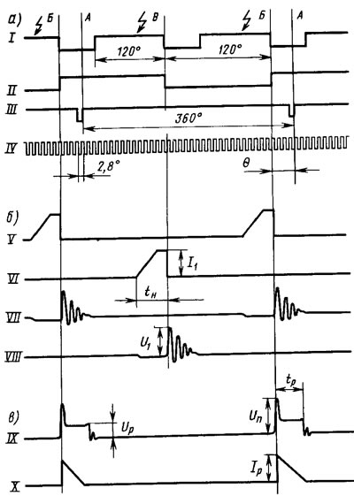
Figure 191. Oscillograms of voltage and current pulses acting at the controller outputs (a), switch (b) and in the secondary circuit of the ignition coil (c): I - signal "Ignition moment"; II - "Channel Selection" signal; III - signal "Start of counting"; IV - signal "Angular impulses"; V - current pulses at the output of channel 1; VI - current pulses at the output of the 2nd channel; VII - voltage pulses at the output of the 1st channel; VIII - voltage pulses at the output of the 2nd channel; IX - voltage pulses; X - current pulses; A - TDC of pistons of the 1st and 4th cylinders; B - ignition timing in cylinders 1 and 4; B - ignition moment in the 2nd and 3rd cylinders; θ - ignition timing angle
Signal "Ignition Timing" or SZ (I, figure 191, a) has an angular pulse duration of (120±2)° along the crankshaft. The moment of spark formation is determined by the pulse cutoff (transition from high to low level).
The "Channel Select" signal or VK (II) has an angular pulse duration of 180° along the crankshaft. The moment of spark formation corresponds in the 1st and 4th cylinders to the transition from a low signal level to a high one, and in the 2nd and 3rd cylinders - from a high level to a low one.
The "Start of Counting" signal or HO (III) is generated once per crankshaft revolution. The transition from low to high level corresponds to the position of the pistons of the 1st and 4th cylinders at TDC
The signal "Angular pulses" or UI (IV) is generated 128 times (by the number of teeth on the flywheel rim) per 1 revolution of the crankshaft. The period of the UI signal is 2.8° along the crankshaft.
All controller outputs are made in the form of an "open collector" transistor structure with a load capacity of no more than 10 mA.
The purpose of the plugs in the controller connector is given in Table 34.
Table 34
| plug No | Purpose of the plug |
| 1 | Output of the control signal of the idle speed control valve |
| 2 | Supply voltage +12 V |
| 3 | Output to the SZ signal switch |
| 4 | Output to the VK signal switch |
| 5 | NO output for diagnostics |
| 6 | Input from carburetor limit switch |
| 7 | Output of the UI for diagnostics |
| 8 | Input NO1 for signal from NO sensor |
| 9 | Input UI1 for signal from UI sensor |
| 10 | General (body) |
| 13 | Output for diagnostics (on the tachometer) SZ |
| 15 | Input for signal from temperature sensor (common) |
| 16 | Input for signal from temperature sensor |
| 18 | Input UI2 for signal from UI sensor |
| 19 | Input HO2 for signal from HO sensor |
Switch
Two-channel, type 42.3734. According to the control pulses (SZ and VK) of the controller, it produces: alternate switching on of the channels and, consequently, the ignition coils;
formation of current pulses during time tn (figure 191, b) accumulation in the primary windings of the ignition coils.
Amplitude of current pulses I ₁ (see waveform V) is equal to 8-10 A, and the accumulation time tK in the crankshaft speed range from 750 to 4500 rpm and a supply voltage of 14 V should be 8-4 ms. The amplitude of voltage pulses U ₁ (see waveform VII) on the output transistors of the switch at the moment of interruption of the primary current (I ₁) is 350-400 V.
Information copied from the portal: VAZbook.ru
The purpose of the output plugs in the plug-in connector of the switches is given in Table 35.
Table 35
| plug No | Purpose of the plug |
| 1 | Output to ignition coil of 2nd and 3rd cylinders |
| 2 | General (body) |
| 3 | Tachometer output |
| 4 | Supply voltage +12 V |
| 5 | Input for VK signal from controller |
| 6 | Input for SZ signal from the controller |
| 7 | Output to ignition coil of 1st and 4th cylinders |
Ignition coil
High energy, type 29.3705, with two high voltage terminals, with open magnetic circuit, molded in plastic.
Two ignition coils are used for contactless distribution of high-voltage voltage. One of them generates high-voltage pulses to the spark plugs of the 1st and 4th cylinders, and the other one to the spark plugs of the 2nd and 3rd cylinders, and the spark discharge occurs simultaneously on both spark plugs. Therefore, during the working cycle (2 crankshaft revolutions) in each cylinder, 2 spark discharges occur. One (working) occurs at the end of the compression stroke, and the second (idle) occurs at the end of the exhaust gas release.
Oscillograms of voltage and discharge current pulses in the secondary circuit of the ignition coil are shown in Figure 191, c.
Synchronization sensors
Inductive, type 14.3847. Designed to synchronize the controller operation with the top dead center of the pistons of the 1st and 4th cylinders (HO sensor) and the angular position of the engine crankshaft (UI sensor) every 1.4° along the crankshaft, i.e. 2, 8°:2 along the crankshaft.
The HO sensor is installed on the clutch housing so that it generates a voltage pulse at the moment of passage of the marker pin pressed into the flywheel in its magnetic field. And this moment corresponds to the TDC position of the pistons of the 1st and 4th cylinders.
The UI sensor generates angular pulses when the flywheel rim teeth (number of teeth—128) pass through its magnetic field. Sensor installation gaps (see figure 195) should be within 0.3-1.2 mm.
The oscillograms of the pulses generated by the NO and UI sensors are shown in Figure 192. The amplitude of the voltage pulses is from 0.2 to 100 V in the crankshaft speed range from 25 to 6000 rpm. The pulse period of the NO sensor is 360° along the crankshaft, and that of the UI sensor is 2.8° along the crankshaft.
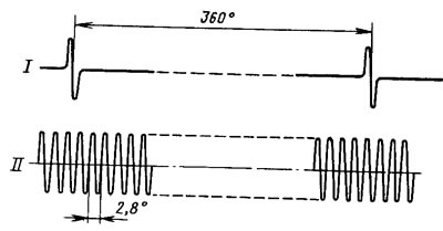
Figure 192. Oscillograms of the reference sensor pulses (I) and angular pulses (II)
Engine Coolant Temperature Sensor
Type 19.3838, linear semiconductor. The voltage drop at the sensor terminals when powered by a constant current of 1.5 mA is numerically equal to (in millivolts) coolant temperature in°K, multiplied by ten.
Example: Let's say the coolant temperature is 0°C (273°K), then:
UD.T = 10-273 = 2730 mV/2.73 V
The switch and spark plugs, interference suppression tips and high-voltage wires are the same as on the VAZ-2108 car.
Warnings
The car uses a high-energy ignition system with extensive use of electronics. Therefore, in order to avoid injury and damage to electronic components, it is necessary to follow these rules:
- when the engine is running, do not touch any elements of the ignition system (commutator, ignition coils and high-voltage wires);
- do not check the ignition system for operability by "sparking" between the spark plug wire tips and the housing. This is dangerous for the inspector and can damage the electronic components;
- do not run low voltage ignition system wires in the same harness with high voltage wires;
- monitor the reliability of the connection to the switch and controller case through the mounting screws. This affects their smooth operation;
- do not disconnect the plug from the switch when the ignition is on, as this may cause increased voltage on individual elements of its circuit and damage it.