Before checking the condition of the clutch drive part, make sure that the working surface of the pressure plate is not damaged (no annular wear, deep scratches or other defects). Then install the casing 2 (figure 75) clutch assembly with pressure plate 3 on a device with intermediate ring 4 of thickness A=8.1 mm. This device imitates a flywheel with a driven disk.
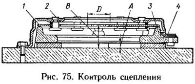
Having secured the clutch housing, perform three clutch disengagement strokes within 5.7-6.7 mm, applying a load to the petals of the pressure spring 1 at a diameter of 34 mm. In this case, measure the amount of pressure plate travel. The disengagement stroke of (5.7±0.1) mm should correspond to a pressure plate travel of at least 1.2 mm. Measure the distance B from the base of the device to the plane of the ends of the petals of the pressure spring. It should be within 27.5-30.5 mm for a new clutch. During clutch operation, this dimension increases due to wear of the disks.
If the disks are worn, repeat the above operations using an intermediate ring with a thickness of A=6.5 mm. The release stroke (5.7±0.1) mm should correspond to a pressure disk offset of at least 1.2 mm. Distance B should be no more than 37 mm.
The original can be viewed on the portal [VAZBOOK]
If the pressure plate travel in both cases is less than 1.2 mm, replace the clutch housing assembly.
Check the condition of the cable. First of all, make sure that the cable moves freely, without jamming, that there is no damage to the cable and sheath coatings, and that there are no breaks in the cable and sheath. Check the fastening and condition of the cable and sheath tips, the antifriction tube, which should protrude from both cable and sheath tips and should not move freely by hand. Check the condition of the leash and protective caps. If the cable or sheath is worn out, if the cable coating is frayed, or if the sheath coating is significantly damaged, replace the cable. If the leash and protective caps are worn out or damaged, replace them. Check the condition of the plastic bushing in the upper cable tip, replace it if necessary.
Check the elasticity of the springs. The springs of the clutch and brake pedals are interchangeable. The length of the spring should be: under a force of (13±2) N—80 mm, under a force of (120±6) N—160 mm.
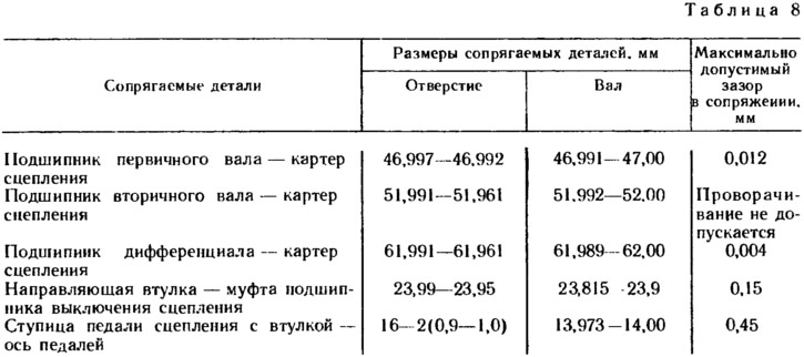
The dimensions of the main mating parts and the limits of permissible wear during operation are given in Table 8.