
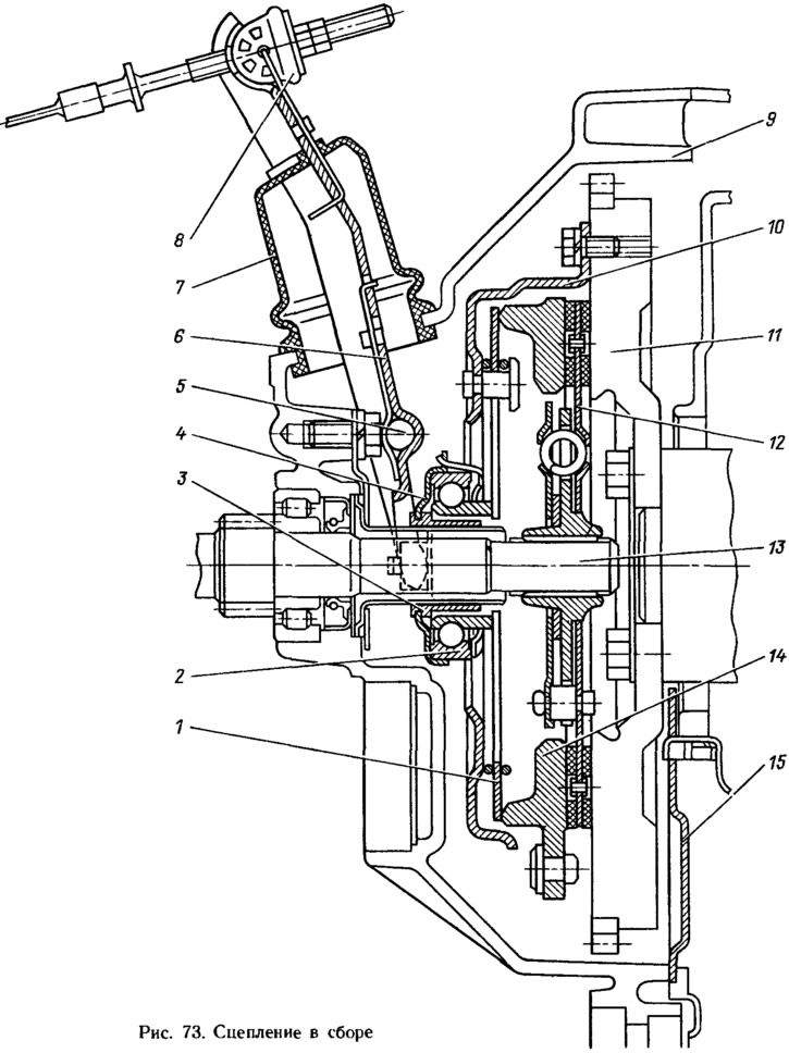
The leading part of the clutch is made as an integral unit, which includes the clutch cover 10, the pressure plate 14, the pressure spring 1 and a number of other parts.
The driven disk 12, complete with a damper, is located on the splines of the input shaft 13 of the gearbox.
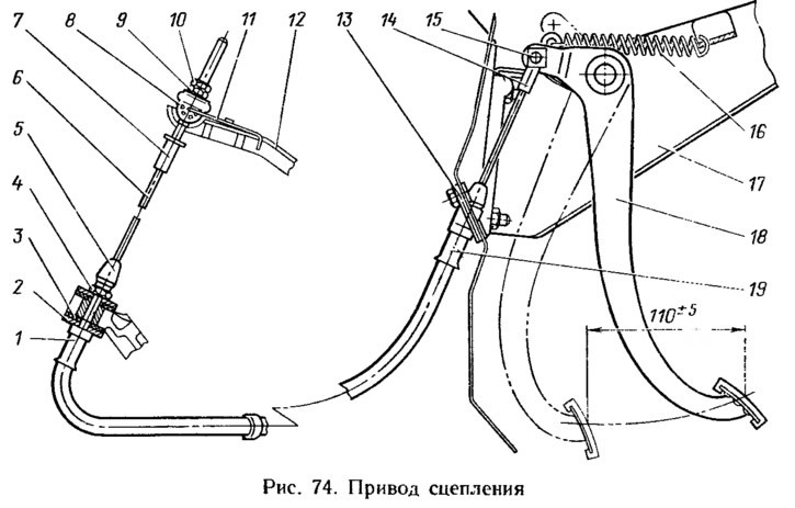
Clutch drive cable with no gap between the clutch release bearing and the pressure spring. There is no free play and a fixed position of the clutch pedal. The main parameter that determines the normal operation of the clutch drive is the clutch pedal stroke, which is adjusted from the pedal to the body when the clutch cable is installed. When the pads of the driven disk are worn, the working stroke of the pedal increases and at some point it becomes necessary to adjust the drive.
The drive consists of a pedal 18 (pic. 74), mounted on a common axle with a brake pedal on bracket 17, and cable 6 as an assembly. The upper tip 14 of the cable is connected through a plastic sleeve to the clutch pedal pin and is fixed with a locking bracket 15, and the lower tip 7 of the cable is connected through the leash 8 to the clutch release fork 12. The leash, with possible movements of the cable tip, is held on the fork by a latch 11. The cable route in the engine compartment is determined by its sheath, the upper tip 19 of which is fixed through the seal 13 on the body front panel. The lower tip 1 of the shell is installed in the socket of the tide cover of the gearbox with damping bushings 3 and is fixed through thrust washers 2 with a nut 4. To protect the inner cavity of the shell from contamination, the tips are equipped with protective caps 5. From sagging, the cable shell is held by a bracket installed in the hole of the front wing mudguard.
Stamped fork 6 (see fig. 73) the clutch release rests on the ball bearing 5 and is held on it by a wire spring attached to the fork. The inner end of the fork is connected to the flange 4 of the clutch release bearing, and the outer end is connected through the leash 8 to the cable.
Bearing 2 ball, with built-in washers. It is installed with a small radial clearance in the clutch 3 of the clutch release bearing. The bearing is pressed against the coupling flange with a wave washer, which is mounted on the four antennae of the flange. This connection allows the bearing «swim», that is, self-align in the clutch, which increases the durability of the contact pair: bearing and pressure spring. The clutch release bearing is constantly pressed against the pressure spring petals with a force of 30-70 N (3—7 kgf), which is provided by the spring 16 (see fig. 74) on the clutch pedal.