To check the condition of the leading part of the clutch, install the housing 2 (Figure 59, 1 of the clutch assembly with the pressure plate 3 on a device with an intermediate ring 4 8.3 mm thick. This device imitates a flywheel with a driven disk. Having secured the clutch housing, perform three disengagement strokes, applying a load of no more than 137.8 kgf to the petals of the pressure spring 1, and measure the amount of travel of the pressure plate. The disengagement stroke of (7±0.1) mm of the ends of the petals must correspond to a disk stroke of at least 1.4 mm.
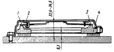
Figure 59. Clutch control
Measure the distance from the base of the device to the plane of the ends of the spring petals. It should be 32.6-34.6 mm for a new clutch. During clutch operation, this dimension increases due to wear of the clutch discs. If it reaches 43 mm or the movement of the pressure disc is less than 1.4 mm, replace the clutch housing together with the pressure disc.
Check the elasticity of the springs. The release fork return spring should have a length of: 102 mm under a force of (23.5±2.4) kgf; 91 mm under a force of (12.3±1.2) kgf; 81 mm in free state.
The length of the clutch release actuator spring should be 30.6 mm under a force of (54.9±0.6) kgf; 44 mm under a force of (31.5±0.7) kgf; 62 mm in free state.
Check the condition of the cable. First of all, make sure that the cable tips, leash and shackle are firmly attached, and that the cable moves freely inside the sheath. Check the condition of the cable sheath, rubber buffers and bushings, protective cover, shackle and leash. If the cable and its other elements are damaged, or if the tips are loose, replace the cable with a new one.
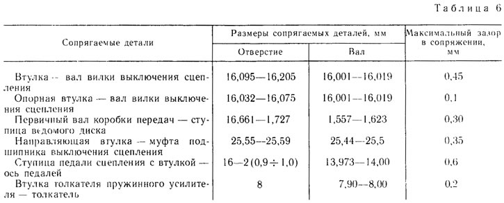
The dimensions of the main mating parts and the limits of permissible wear during operation are given in Table 6.