




The steering shaft is composite and consists of an upper 13 (Fig. 183) and an intermediate 20 shaft. The worm shaft 18 and the upper shaft 13 are connected to each other by an intermediate shaft 20 with cardan joints at the ends. The joints on needle bearings are non-separable.
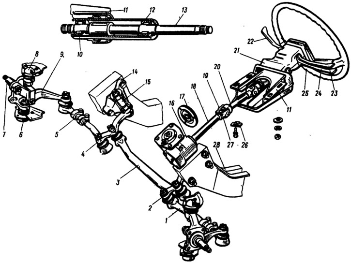
Fig. 183. Steering:
1 - side pull; 2 - bipod; 3 - medium thrust; 4 - pendulum lever; 5 - adjusting coupling; 6 - lower ball joint; 7 - right steering knuckle; 8 - Upper ball joint of the front suspension; 9 - right steering knuckle arm; 10 - Upper shaft bearing; 11 - Steering shaft mounting bracket; 12 - bracket pipe; 13 - upper steering shaft; 14 - pendulum arm bracket; 15 - pendulum lever axis; 16 - steering gear housing; 17 - shaft seal; 18 - worm shaft; 19 - cardan joint; 20 - intermediate steering shaft; 21 - facing casing; 22 - Windscreen wiper and washer switch lever and headlight unit; 23 - headlight switch lever; 24 - direction indicator switch lever; 25 - steering wheel; 26 - Front body fixing plate; 27 - hinge tie bolt; 28 - body side member.
The upper shaft is installed in the bracket pipe 11 on two needle bearings with rubber bushings. The bearings in the pipe are rolled. Bracket 11 is attached to the body panel bracket at four points: from below with bolts with fixing plates 26, from above - on welded bolts with nuts and washers.
In a frontal collision, the edges of the fixing plates are deformed and slip through the holes in bracket 11. Due to the folding of the steering shaft, the steering wheel moves away from the driver's chest area, which reduces the likelihood and severity of injury.
Worm shaft (this type of steering has) has a greater length. In the lower part of the worm shaft, as well as on the end of the housing 7 (Fig. 184) of the steering gear, marks are made in the form of marks B and C, along which the roller of the pitman shaft is installed in the middle of the worm. When these marks are aligned, the steering wheel hub should be horizontal.
The original can be seen on the website VazBook.ru
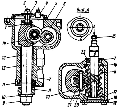
Fig. 184. Steering mechanism:
1 - Bipod shaft adjusting screw plate; 2 - adjusting screw; 3 - lock nut: 4 - plug; 5 - steering gear housing cover; 6 - worm; 7 - steering gear housing; 8 - bipod; 9 - bipod mounting nut; 10 - spring washer; 11 - knuckle shaft seal; 12 - bushing; 13 - bipod shaft; 14 - roller of the bipod shaft; 15 - worm shaft; 16, 17 - worm bearings; 18 - adjusting shims; 19 - lower crankcase cover; 20 - roller axis: 21 - roller bearing; 22 - worm shaft seal; B, C - marks.
Due to the cardan joints on the intermediate shaft, there is no longer any need to install adjusting washers between the steering gear housing and the body side member to adjust the alignment of the connected shafts. To reduce the effort on the steering wheel, roller 14 is mounted on a double-row ball bearing 21.
The steering gear parts are interchangeable with other VAZ car models.