
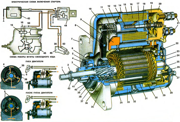
1. Anchor shaft. 2. Retaining ring. 3. Drive gear. 4. Freewheel roller. 5. Plate with bent petals. 6. Freewheel hub with drive cage. 7. Front cover. 8. Axis of gear drive lever. 9. Plug. 10. Drive lever. 11. Anchor spring. 12. Anchor of the traction relay. 13. Return spring. 14. Body (yoke) traction relay. 15. Holding winding of the traction relay. 16. Retracting winding of the traction relay. 17. The rod of the contact disk. 18. Traction relay core. 19. Contact disk. 20. Traction relay cover. 21. Contact bolts. 22. Collector. 23. Brush holder. 24. Bushing of the armature shaft. 25. Lock washer. 26. Brush. 27. Coupling bolt. 28. Casing. 29. Back cover. 30. Stator winding. 31. Anchor core. 32. Corps. 33. Stator pole. 34. Restrictive ring. 35. Pressure ring. 36. Buffer spring. 37. Freewheel cover. 38. Pusher. 39. Pusher spring. 40. Half ring. 41. Gear bushing. 42. Restrictive ring. 43. Battery. 44. Auxiliary starter relay. 45. Starter switch. 46. Starter.
Technical specifications:
- Rated power, kW - 0.9
- The strength of the current consumed at rated power, A - 230
- Direction of rotation (gear side) - Left
- Starter weight, kg - 5
To spin the engine crankshaft up to the frequency at which the engine starts to run (i.e. to start the engine), starter type 39.3708 is used. He turns the crankshaft with a gear behind the flywheel ring gear. The starter is mounted on the left side of the engine (in the direction of the car) and is attached to the clutch housing on one side with a nut, and on the other with a bolt. Moreover, the bolt passes through the clutch housing and is wrapped in the engine block.
Interchangeable starters 1111-3708010-05 made in Belarus and AZE-1517 made in Slovenia can also be used. But only the starter 39.3708 is described here, as the main one for cars «Oka».
Starter 39.3708 is a four-pole DC motor with mixed excitation, with remote electromagnetic activation and freewheel roller clutch. It consists of the following main parts: housing 32 (stator), anchors with freewheel and drive gear 3, two covers 7 and 29 and a traction relay. The housing and covers with casing 28 are connected together by two tie bolts.
The body 32 of the starter is made of mild steel strip, rolled into a ring and butt welded. Inside the housing, four steel poles 33 with field winding coils are fixed with screws. The case with poles and winding is a starter stator. Three winding coils (serial) connected to the armature winding in series, and one (shunt) - in parallel. Therefore, the excitation of the starter is called mixed. It allows you to get a large torque in the inhibited state and a relatively low frequency of rotation of the armature at idle, which reduces wear on the bearing bushings and facilitates the operation of the freewheel.
The same current flows through the serial stator coils as through the armature winding, that is, the main current consumed by the starter. And under difficult starting conditions, it can reach 310 A. Therefore, serial coils are wound with copper tape with a large cross-sectional area. A relatively small current flows through the shunt coil. Therefore, it is wound with copper wire in enamel insulation. Coils are braided with cotton tape and impregnated with varnish.
An armature assembled on shaft 1 rotates between the stator poles. The armature core 31 is made of electrical steel plates pressed onto the middle part of the shaft. Along the circumference of the core there are longitudinal grooves, insulated with cardboard, in which there is an armature winding made with copper tape. The winding ends are soldered to collector plates 22.
A feature of the starter 39.3708 is the end collector 22, pressed onto the back of the armature shaft. Such a collector has the form of a disk with contact sectors, to which brushes are pressed in the direction of the starter axis. The end collector promotes more stable and long work of brush contact. In addition, the use of such a collector made it possible to reduce the length and weight of the starter, as well as the consumption of scarce copper.
The armature shaft rotates in two ceramic-metal bushings. The rear sleeve * 24 is pressed into the cover 29, and the front one is located in the clutch housing and the front end of the armature shaft enters it when the starter is installed in the clutch housing socket. From axial movement, the armature shaft is fixed with a lock washer 25, which is placed in a groove at the rear end of the shaft.
At the front end of the armature shaft there is a freewheel with gear 3 of the drive. The purpose of the clutch is to transmit torque from the starter armature shaft to the flywheel crown when the engine is started, and after starting, to disconnect the armature shaft and the drive gear, since after starting the engine starts to rotate the armature shaft at a high frequency and can damage it.
The freewheel clutch consists of a hub 6 with a drive cage and a driven ring, which is integral with the gear 3. The drive cage has three grooves profiled along the radius, in which there are hardened steel rollers 4. In the wide part of the groove, the rollers can rotate freely, and in the narrow part - wedged between the leading clip and the driven ring. Springs 39 through L-shaped pushers 38 press the rollers towards the narrow part of the groove. The other end of the spring rests on the bent petals of the plate 5. Two thrust half rings 40 hold the driven ring inside the drive cage. Half rings 40, together with the plate 5 and the leading cage 6, are rolled in a steel casing 37.
Two rings are installed on the coupling hub - pressure 35 and restrictive 34, pressed by a buffer spring 36 to the retaining ring on the hub. Between the rings 35 and 34 are the fingers of the lever 10 of the drive. The coupling hub has internal screw splines and can, by turning, move along the screw splines of the armature shaft, while simultaneously moving the drive gear 3 at the front end of the armature shaft.
Covers 7 and 29 are cast from aluminum alloy. In cover 7, on axis 8, a steel stamped drive lever 10 is fixed, which transmits traction force from relay armature 12 to pressure ring 35. Plastic brush holder 23 with four copper-graphite brushes is attached to cover 29. The conclusions of the two brushes are connected to the cover (i.e. with mass). This «negative» brushes. The output of the serial coils of the stator winding is connected to the other two brushes. These are brushes «positive», through them current is supplied to the armature winding. Outside, the cover 29 is closed with a stamped steel casing 28.
The traction relay is attached with two screws to the cover 7. With its help, the starter is remotely controlled. The relay closes the power circuit of the armature and stator windings, and also through lever 10 engages gear 3 with the flywheel crown. The relay is two-winding, has a retracting 16 and holding 15 windings wound in one direction. The beginning of the windings are soldered to the plug «50» on the relay cover. The end of the holding winding is welded to the relay flange (i.e. connected to ground), and the end of the retractor is connected to the lower contact bolt of the relay.
The design of the relay is non-separable. The coil with windings and the core with the relay flange are rolled in a steel case 14. The relay contacts are made in the form of two powerful copper bolts 21, fixed with nuts on a plastic cover 20. The stator winding leads are connected to the lower contact bolt, and the wire from the battery is connected to the upper one. The contact bolts are closed with a copper contact disk 19.
Starter operation
The starter is switched on using auxiliary relay 44 type 113.3747-10, installed on the left under the instrument panel near the fuse box. The relay device is described on sheet 35. It relieves contacts «30» and «50» ignition switch from the high current consumed by the windings of the traction relay. This improves the reliability of the ignition switch and increases its durability.
When the key is turned to position II («Starter») contacts close «30» and «50» ignition switch 45 and through the winding of the auxiliary relay 44, a current begins to flow, which acts in the circuit: «plus» battery - plug «30» auxiliary relay - closed contacts «30» and «50» ignition switch - plug «85», winding and plug «86» auxiliary relay 44 - ground.
The contacts of the auxiliary relay close under the action of the current in its armature, and through them the current flows into the windings of the starter traction relay along the circuit: «plus» battery - plug «30» contacts and plug «87» auxiliary relay - plug «50» starter. Here the current path splits into two parallel branches. One passes through the holding winding 15 of the traction relay and to ground, and the second passes through the retracting winding 16, through the stator and armature windings, also to ground.
Under the action of the current flowing through the windings of the traction relay, a magnetic force arises (about 10 kgf), retracting the armature 12 of the relay until it touches the core 18. The armature retracts and pushes the rod 17 with the contact disk 19, which closes the contact bolts 21. The dimensions of the rod are selected so that the contact bolts are closed even before the relay armature touches the core and during the further armature stroke the spring of the contact disk is compressed, pressing it harder against the contact bolts.
At the same time, the relay armature with lever 10 moves the freewheel with gear 3 forward. Moving, the clutch hub turns on the screw splines of the armature shaft and turns gear 3. Due to the rotation of the gear and the chamfers on its teeth, as well as the transfer of force through the buffer spring 36, the impact of the gear in flywheel crown and facilitates its engagement. The dimensions of the parts of the relay and the drive are calculated in such a way that the closing of the contact bolts occurs when the gear 3 is only partially engaged with the flywheel crown.
When the contact bolts are closed, the solenoid winding of the relay is de-energized, since both ends of it are connected to «a plus» battery 43. But since the armature of the relay is already pulled in, a relatively small magnetic flux is required to hold it in this position, which is provided by one holding winding 15.
Through the closed contacts of the traction relay, a current flows, feeding the stator and armature windings. As a result of the interaction of the magnetic fields created by this current, the starter armature begins to rotate. Its rotation through the screw slots is transmitted to the hub and the leading cage 6 of the coupling. Since the rollers 4 are displaced by the springs into the narrow part of the groove of the drive cage, they are wedged between the cage and the clutch driven ring. Therefore, the torque from the armature shaft is transmitted through the clutch and gear to the flywheel crown. At the same time, as a result of gear braking and armature rotation, the coupling hub is screwed off the splines of the armature shaft and the gear is filled forward until it stops in the restrictive ring 42, fully engaging with the flywheel crown.
After starting the engine, its excess torque accelerates the flywheel, as a result of which the speed of gear 3 begins to exceed the speed of the starter armature. Clutch driven ring (combined with gear) drags the rollers into the wide part of the groove of the drive cage 6, compressing the springs 39. In this part of the groove, the rollers rotate freely without jamming, and the torque from the engine flywheel is not transmitted to the starter armature shaft.
After the key is returned to position 1 («Ignition»), auxiliary relay 44 turns off. Its contacts open, and the power supply circuit of the starter traction relay from the auxiliary relay is interrupted. Now the current goes through the following circuit: «plus» battery - closed contacts of the traction relay - retracting 16, and then holding 15 windings of the traction relay - ground. Since the direction of the current in the turns of the windings turns out to be opposite, the magnetic fluxes created by the windings cancel each other out and the relay core is demagnetized. The armature of the relay is pressed back to its original position by return springs and the relay contacts open, turning off the power to the armature windings and the starter stator.
At the same time, the armature of the traction relay with lever 10 moves the freewheel back and disengages the gear from the flywheel crown. The starter armature is braked by the forces of friction of the brushes on the collector and quickly stops.
The starter is designed for short-term operation. Therefore, in order not to overheat the winding of the traction relay, when starting the engine, it is recommended to turn on the starter for no more than 10... 15 s. Usually the engine starts on the first try, but if this does not happen, then the starter should be turned on again after 20... 30 s. If after three starter activations the engine does not start, then the power supply or ignition system should be checked and the malfunction preventing the engine starting should be eliminated.