
The vehicles are equipped with safety steering with rack and pinion steering. This type of steering is compact and simple in design, more technologically advanced in manufacturing and goes well with the front-wheel drive layout of the car and the transverse arrangement of the power unit. In order to increase passive safety, the steering wheel has a damping element.
The steering consists of a steering mechanism and a steering gear.
Steering gear 18 (pic. 76) assembled with rods 1 and 8 of the steering drive is attached with two brackets 9 to the front panel of the body. To dampen vibrations, rubber cushions are installed between the crankcase and the panel, as well as on both crankcase supports.
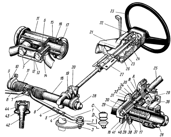
Pic. 76. Steering assembly:
1 - tie rod end; 2 - ball joint of the tip; 3 - rotary lever; 4 - nut; 5 - adjusting rod; 6 - left steering rod; 7 - bolts for fastening the steering rods to the rack; 8 - right steering rod; 9 - bracket for mounting the steering mechanism; 10 - support of the steering mechanism; 11 - protective cover; 12 - connecting plate; 13 - locking plate; 14 - rubber-metal hinge; 15 - sealing ring; 16 - rail support sleeve; 17 - rail; 18 - steering gear housing; 19 - coupling bolt; 20 - plastic clutch; 21 - upper part of the facing casing; 22 - damper; 23 - steering wheel; 24 - ball bearing; 25 - steering shaft; 26 - lower part of the facing casing; 27 - steering shaft mounting bracket; 28 - protective cap; 29 - roller bearing; 30 - drive gear; 31 - ball bearing; 32 - retaining ring; 33 - protective washer; 34 - sealing ring; 35 - bearing nut; 36 - anther; 37 - stop sealing ring; 38 - stop ring nut; 39 - rail stop; 40 - spring; 41 - stop nut; 42 - ball joint pin; 43 - protective cap; 44 - ball pin insert; A - mark on the crankcase of the steering mechanism; B - mark on the anther.
The steering box is cast from aluminum alloy together with the left support. A drive gear 30 is installed in the crankcase cavity on ball 31 and roller 29 bearings. The ball bearing on the gear shaft is fixed with a retaining ring 32. The outer ring of the bearing is pressed against the end of the crankcase seat with a nut 35, in the groove of which a sealing ring 34 with a protective washer 33 is installed. in the crankcase with a washer and is closed with anther 36, which is mounted on the drive gear shaft. Marks A and B are made on the crankcase of the steering mechanism and on the anther for the correct assembly of the steering mechanism.
Gear 30 is engaged with rack 17, which is pressed against the gear by spring 40 through ceramic-metal stop 39. This stop is sealed in the crankcase by rubber ring 37. The spring is pressed by nut 41 with retaining ring 38, which prevents the nut from unscrewing. Due to the spring-loaded stop 39, backlash-free engagement of the gear with the rack is ensured over the entire stroke of the latter. The rail rests on stop 39 at one end, and on a split plastic sleeve 16 at the other end. There are grooves on the outer surface of the sleeve into which rubber sealing rings 15 are installed. thereby the sleeve against axial displacement and against rotation.
A protective cap 28 is put on the crankcase of the steering gear on the left side, and a pipe with a longitudinal groove is pressed on the right side. Bolts 7 pass through the groove of the pipe and the holes of the protective cover 11, fastening the rods 6 and 8 of the steering gear to the rack. Between themselves, the bolts are connected by a plate 12. Both bolts pass through rubber-metal hinges 14, pressed into the heads of the rod ends. The bolts are fixed with a locking plate 13.
The travel of the rail is limited on one side by a ring pressed onto the rail, and on the other, by a bushing of the rubber-metal hinge 14 of the thrust. In this case, both the ring and the sleeve abut against the crankcase of the steering mechanism. The cavity of the crankcase of the steering mechanism is protected from contamination by a corrugated cover 11, which is fastened with two plastic clamps, as well as a protective cap 28.
The steering shaft 25 is connected to the drive gear 30 by an elastic coupling 20. The upper part of the shaft rests on a ball radial bearing 24 with a plastic sleeve, which is pressed into the tube of the bracket 27. At the upper end of the shaft, on the splines through the damping element 22, the steering wheel 23 is fastened with a nut.
Bracket 27 for mounting the steering shaft is attached at four points to the body bracket. The steering column switch connector is mounted on the bracket tube 27, and the contact part of the sound signal is fixed on the lower end of the damping element. The steering column switch and the sound signal switch are closed by a protective casing, consisting of the upper 21 and lower 26 parts, interconnected by screws.
The steering drive consists of two horizontal rods 6 and 8 and swivel arms 3 of the telescopic struts of the front suspension. Composite pulls. When adjusting the toe of the front wheels, the length of each rod is changed by a tubular rod 5, which is screwed onto the rod ends and locked with nuts 4.
In the head of the outer tip there are parts of the ball joint, consisting of an insert 44 and a ball pin 42, a spring and a protective cap 43. The plastic insert, together with the pin, is constantly pressed by a spiral spring against the conical surface of the tip bore. Due to the presence of a longitudinal section of the liner, the gap between the liner and the finger is automatically selected. The other end of the spring rests against a plug rolled into the tip. The hinge cavity is sealed with a protective cap 43, which at one end enters the bore of the tip, and the other is tightly fitted onto the pin 42.
Swivel arm 3 is welded to the body of the front suspension strut. It has a bushing with a conical hole for the pin 42 of the ball joint.
The parts of the steering mechanism are lubricated with Fiol-1 grease, which is put into the crankcase of the mechanism and on the parts during assembly of the mechanism, and the parts of the ball joint are lubricated with SRB-4 grease, also during assembly. During the operation of the car, the steering parts are not additionally lubricated, with the exception of cases of damage to the protective covers and caps, when it is necessary to disassemble the steering with the replacement of grease, caps, covers, and possibly other damaged parts. All these operations should be carried out at a service station.