Contents: Steering gear ↓ Steering drive ↓
The described vehicles are equipped with the same type of steering control, except that the VAZ-21011 and VAZ-21021 vehicles are equipped with steering wheels of a different external design.
Steering gear
Includes a worm gear located in the crankcase 13 (Fig. 124), steering wheel 16, steering shaft 14 and fastening parts.
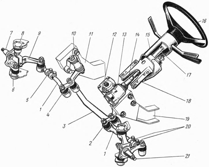
The steering wheel is plastic, reinforced with a steel frame. The wheel has a horn switch, the contact part of which is covered with a plastic cover. The steering wheel hub has a hole with a double recess, and the shaft 14 has a double spline, due to which the steering wheel is attached to the shaft with a nut in only one position.
The steering shaft is connected to the worm shaft with its tip using splines and a tie bolt. The upper part of the shaft rests on a plastic bushing installed in the pipe 17 of the upper shaft support. This pipe is inserted into the bracket 18 and secured in it with a clamp, which is tightened with a bolt. The turn signal and headlight switch is attached to the flange of the upper shaft support pipe.
The bracket 18 of the steering shaft is attached to the body with four bolts. The bracket and the upper part of the shaft are covered with plastic covers 15.
[The material is posted on the online resource: vazbook.ru]
The steering gear housing is attached to the left side member 19 of the body from the inside of the engine compartment with three bolts. Adjusting washers are installed between the housing and the side member, the selection of which achieves the coaxiality of the worm shaft and the steering shaft.
In the housing 7 (Fig. 125) there is a worm 6, which engages with a double-ridge roller 12 of the shaft 11 of the pitman arm. The gear ratio of the worm pair is 16.4. The worm is pressed onto the shaft 13 and rotates in the upper 14 and lower 15 bearings, with the inner bearing races being the end surfaces of the worm, on which the raceways for the bearing balls are made. The axial clearance in the worm bearings is adjusted by selecting gaskets 16 between the housing and cover 17. These gaskets are supplied as spare parts in two sizes: 0.1 and 0.15 mm thick.
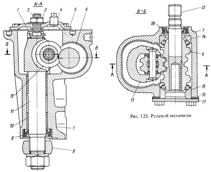
The pitman arm shaft rotates in two bronze bushings 10 pressed into the steering gear housing. At the upper end of the shaft, roller 12 rotates on a needle bearing, and pitman arm 8 is put on the lower end of the shaft, which has conical splines. There are two double depressions in the splined opening of the pitman arm, and two double projections on the shaft. Therefore, the pitman arm can be installed on the shaft only in one specific position.
The position of the bipod shaft, which ensures correct engagement of the roller with the worm, is adjusted by screw 2. The axial clearance between the screw head and the shaft groove is eliminated by selecting adjusting plates 1, which are supplied as spare parts in eleven sizes with a thickness from 1.95 to 2.20 mm.
TAd-17i oil is poured into the steering gear housing up to the level of the filler hole in cover 5, closed by plug 4 (12, in Fig. 124).
Steering drive
Includes three rods - middle 3 (see fig. 124) and two outer 1, as well as pitman arm 2, pendulum arm 4 with bracket 10 on side member 11 and pivot arms 9 trunnions 7 and Middle rod 3 is solid, has ball joints at the ends for connection with the pendulum arm and steering pitman arm. Each outer rod consists of two threaded ends connected to each other by adjusting coupling 5. Couplings are fixed on rods by means of two tightening clamps 20. By rotating coupling 5 the length of the lateral rod changes when adjusting the toe-in of the front wheels. Ends of outer rods are connected by means of ball joints to levers 9 of pivot trunnions, to pendulum arm and to steering pitman arm 2. Pivot trunnions rotate in lower 6 and upper 8 suspension joints.
The ball joints of the rods have a steel pin 1 (Fig. 126), the spherical head of which is located in a conical plastic insert 4. Spring 5 presses the insert to the housing 3 and creates tension in the connection of the pin with the insert and the rod end.
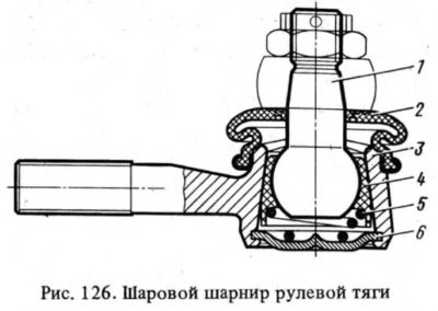
Ball joints during assembly are filled with SRB-4 grease and sealed on one side with a plug 6 rolled in the rod tip, and on the other — with a rubber protective cap 2. Replenishment or replacement of the lubricant during vehicle operation is not required.
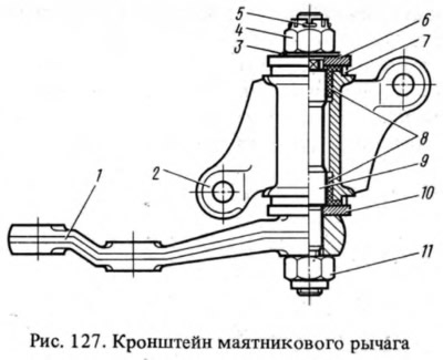
Bracket 10 (see fig. 124) the pendulum arm is secured with two bolts to the right side member of the body opposite the steering gear housing. Two plastic bushings 8 are installed in bracket 2 (Fig. 127), in which axle 9 rotates. Litol-24 grease is added to the bracket during assembly. It does not require replenishment or replacement during operation.
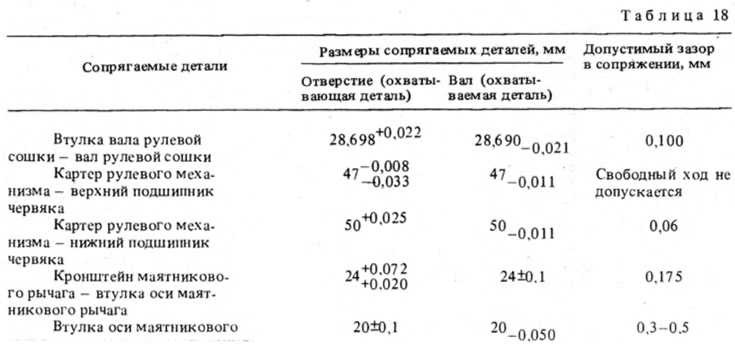
The dimensions of the main mating parts and the limits of permissible wear are given in Table 18.