




Contents: Engine 2105 ↓ Engines 2101, 2103 ↓
Engine 2105
Wash the engine in a washing machine, install it on a disassembly stand and drain the oil from the crankcase.
Remove the carburetor by disconnecting the hoses and throttle drive rod from it, remove the fuel pump and ignition distributor. Key 67.7812.9514 (tubular end 21 mm) remove the spark plugs and coolant temperature gauge sensor.
Remove the alternator and coolant pump drive belt, then the alternator with the bracket.
After disconnecting the heater coolant supply line from the pump and the outlet manifold, remove the coolant pump.
Remove the cooling jacket outlet pipe and the liquid drain pipe to the heater from the cylinder head.
Using tool A.60312, unscrew and remove the oil filter with the gasket. Unscrew the oil pressure indicator lamp sensor.
Remove the crankcase breather cover, oil pan and oil pump; remove the oil separator drain pipe retainer attached to the bottom surface of the cylinder block; remove the crankcase ventilation oil separator.
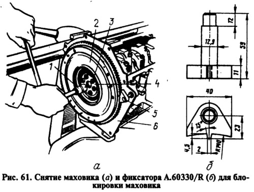
Remove the generator drive pulley 12 (Fig. 60) from the crankshaft. To do this, block the flywheel from turning with the A.60330/R lock (Fig. 61) and unscrew it with the A.50121 key (38 mm socket) bolt 13 (see fig. 60) at the front end of the crankshaft.
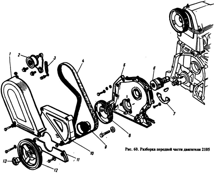
Remove the upper 1, middle 10 and lower 11 protective covers of the camshaft belt drive. Remove the spring 3 of the tension roller bracket 2. Unscrew the bolts, remove the bracket with the tension roller, belt 4, and then toothed pulley 9 from the crankshaft.
Using tool 67.7811.9509 to hold the accessory drive shaft pulley and the camshaft pulley from turning, unscrew their mounting bolts and remove the pulleys. Remove cover 5 of the camshaft drive with the gasket, then thrust flange 7 and accessory drive shaft 6.
Remove the cylinder head cover with the gasket and the bearing housing assembly with the camshaft, seal holder and thrust flange. If necessary, unscrew the nuts separately on the workbench, remove the seal holder, thrust flange and remove the camshaft from the bearing housing. This must be done carefully so as not to damage the bearing housing support surface.
Loosen the cylinder head mounting bolts and remove it together with the exhaust manifold and intake pipe.
After unscrewing the connecting rod bolt nuts, remove the connecting rod caps with the liners and carefully remove the pistons with the connecting rods through the cylinders. When performing this operation, mark the piston, connecting rod, and main and connecting rod bearing liners so that they can be installed in their original place during assembly.
Install the retainer 5 into the cylinder block hole (fig. 61, a) A.60330/R, using key 1, unscrew bolts 3, remove washer 4 and flywheel 2 from the crankshaft, and then front cover 6 of the clutch housing.
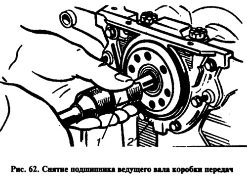
Using the A.40006 1 pusher (Fig. 62) with a collet tip, remove the gearbox input shaft bearing from the socket in the crankshaft. Remove the holder 2 of the rear crankshaft oil seal.
After unscrewing the main bearing cap bolts, remove them together with the lower bearing shells, then remove the crankshaft, upper bearing shells and thrust half rings on the rear support.
Engines 2101, 2103
The disassembly procedure for these engines differs in the operations for disassembling the front part of the engine, where the camshaft chain drive is located. Before removing the generator drive pulley from the crankshaft, all disassembly operations are the same as on the 2105 engine.
After removing the pulley, perform the following operations:
- remove the cylinder head cover with gasket and the camshaft chain drive cover;
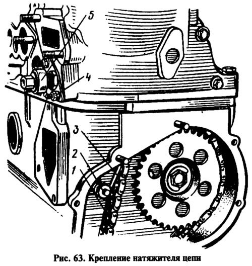
- unscrew the bolts securing the camshaft sprockets and the auxiliary drive shaft. Loosen the cap nut 5 (Fig. 63) of the chain tensioner 1, unscrew the nuts 4 securing it to the cylinder head, remove the tensioner and, having unscrewed the bolt 2, remove the shoe 3 of the chain tensioner;
- unscrew the chain limiting pin, remove the camshaft sprockets and auxiliary drive shaft and take out the chain. Unscrew the bolts and remove the chain guide;
- loosen the nuts of the camshaft thrust flange mounting studs. After unscrewing the mounting nuts, remove the camshaft bearing housing;
- after unscrewing the stud nuts and removing the thrust flange, carefully, so as not to damage the surface of the bearing housing supports, remove the camshaft;
- unscrew the cylinder head mounting bolts and remove it together with the exhaust manifold and intake pipe;
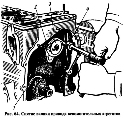
- key 4 (fig. 64, 10 mm socket wrench) unscrew the two bolts 2 securing the thrust flange 1 of the auxiliary drive shaft, remove the flange and take the shaft 3 out of the cylinder block. Use a universal puller to remove the sprocket from the crankshaft.
Next, the pistons are removed, the flywheel and crankshaft are removed, as on the 2105 engine.