
Camshaft drive belt tension adjustment
On engines 2105, the belt tension is adjusted in the following order:
- Remove the upper protective cover of the belt drive. Loosen the bracket mounting bolts 2 (rice. 71) tension roller 1 and smoothly turn the crankshaft 2-3 turns in the direction of rotation. In this case, the spring 3 will automatically set the required belt tension.
Rotate the shaft smoothly, keeping the belt under constant tension, and do not allow it to loosen when the shaft stops. Then tighten the bolts of the bracket 2 of the tension roller, first the right and then the left, install and secure the upper protective cover of the camshaft belt drive.
Chain tension adjustment on engines 2101, 2103 is carried out in the following order:
- Loosen cap nut 1 (see fig. 25) tensioner. Turn the crankshaft 1-1.5 turns in the direction of rotation, while the tensioner springs will automatically set the correct chain tension. After that, tighten the cap nut 1 of the tensioner.
Adjusting the gap between the levers and camshaft cams
Gap adjustment must be carried out very carefully. The gap is adjusted on a cold engine, after adjusting the belt tension (chains) camshaft drive. After adjustment, the gap should be 0.14-0.17 mm.
Adjustment is carried out in the following order:
- Disconnect the wires from the battery, remove the air filter and close the carburetor neck with a technological plug. Disconnect the carburetor throttle linkages from the intermediate lever on the cylinder head cover and the choke cable from the carburetor.
- Remove the top toothed belt guard (on engine 2105) and cylinder head cover with gasket. Inspect the surface of the camshaft cams: they should not have scuffs, shells, wear and deep scratches.
- Turn the crankshaft clockwise by the pulley mounting bolt until the marks on the pulley match (asterisk) camshaft with a mark on the bearing housing (see fig. eleven). In this case, the end of the compression stroke will be in the 4th cylinder. In this position, adjust the clearance at the exhaust valve of the 4th cylinder (8th cam) and inlet valve of the 3rd cylinder (6th cam).
- Holding the adjusting bolt 2 with a wrench (rice. 72) lever, loosen the locknut 3 with another wrench, insert a flat feeler gauge A.95111 between the lever and the camshaft cam (I) 0.15 mm thick and 30 mm wide, and by screwing or unscrewing the adjusting bolt and then tightening the lock nut, ensure that when the lock nut is tightened, the probe enters with a slight pinch. Then, sequentially turning the crankshaft 180°, adjust the clearances at the intake valve of the 4th and exhaust valve of the 2nd cylinder, then at the intake valve of the 2nd and exhaust valve of the 1st cylinder, then at the intake valve of the 1st and exhaust valves of the 3rd cylinders.
Install all parts removed from the engine and adjust the carburetor air and throttle actuators.
Setting the ignition timing
To check the ignition timing, there are marks 1, 2, 3 (rice. 73) on the cover of the timing mechanism drive and mark 4 on the crankshaft pulley, corresponding to the T.M.T. pistons in cylinders 1 and 4.
It is convenient to check and set the ignition timing using a stroboscope. For this:
- connect clamp «+» stroboscope with terminal «+B» ignition coils, and a ground clamp with a terminal «—» battery;
- insert an adapter for connecting a strobe lamp between the spark plug wire of the 1st cylinder and the spark plug, mark mark 4 on the crankshaft pulley with chalk for better visibility and start the engine, directing the flashing stroboscope light stream to the mark on the pulley, which, when the ignition timing is correctly set at idle engine should be against mark 2 on the cover of the timing mechanism drive. If the marks do not match, then stop the engine, loosen the distributor mounting nut and turn it to the required angle.
To increase the ignition timing, turn the distributor housing counterclockwise, and to decrease it, turn it clockwise, then check the ignition timing again.
If you have a diagnostic stand with an oscilloscope, use it to check the ignition timing, proceeding as described in the instructions for the stand.
Adjusting the tension of the alternator drive belt and coolant pump
Check the belt tension by bending between the pulleys. With normal belt tension, the deflection under a force of 10 kgf between the pulleys of the generator and the pump should be within 10-15 mm or 12-17 mm between the pump pulleys and the crankshaft.
To increase the belt tension, loosen the nut securing the alternator to the tension bar, move it away from the engine and tighten the nut. The belt must not be over-tensioned so as not to cause an increase in loads on the bearings of the generator and pump.
Carburetor Drive Adjustment
With the pedal fully depressed 16 (see fig. 46) the first chamber throttle must be fully open and the throttle lever must not have any extra travel. When the pedal is released, the throttle should be fully closed. If not, adjust by changing the length of the rod 8, unscrewing or wrapping its tip. At the same time, check and adjust, if necessary, the length of the rod 6, in which the center-to-center distance of the tips should be 80 mm.
Fasten the air damper drive rod and its shell so that when the handle 1 is fully extended, the damper is completely closed, and when the handle is recessed, it is completely open.
Engine idle adjustment
Adjustment elements include 2 screw (pic. 74, a) quality (composition) mixture and mixture quantity screw 1 for carburetors 2105-1107010 and 2107-1107010. So that the owner does not violate the factory adjustment, restrictive plastic bushings are pressed onto the screws (pic. 74b), allowing you to turn the screws only half a turn.
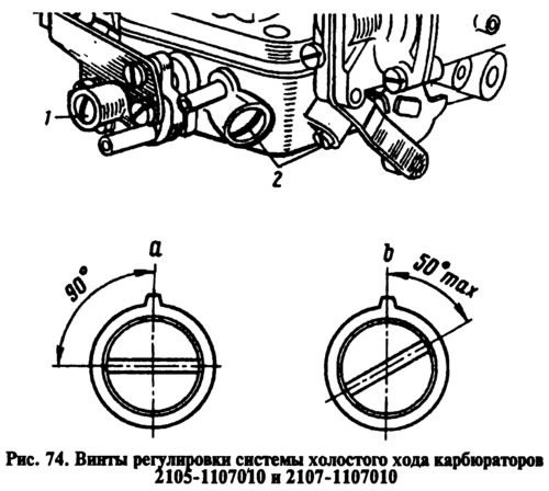
If the bushings fail to adjust the carbon monoxide content (SO) in the exhaust gases, then, turning out, break the bushings, remove them and wrap the screws in place.
Note. Blue bushings are installed at the factory, and red bushings at service stations.
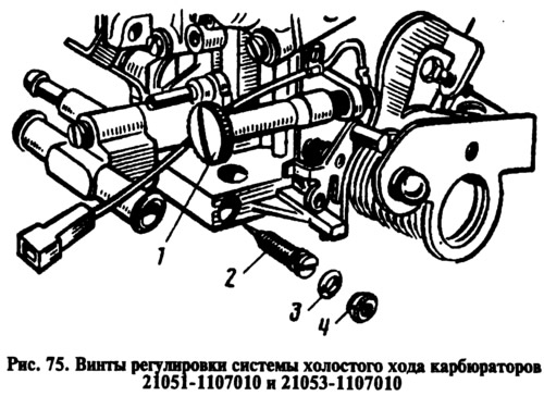
For carburetors 21051-1107010 and 21053-1107010, idle speed adjustment includes adjusting screw 2 (pic. 75) quality (composition) mixture and adjusting screw 1 of the mixture amount. Adjusting screw 2 with O-ring 3 is closed with plug 4. To gain access to the screw, it is necessary to break the plug.
Adjust the idle speed on a warm engine (coolant temperature 90-95°C, with adjusted gaps in the gas distribution mechanism and with a correctly set ignition timing.
Adjust in the following order:
- screw 1 adjust the speed of the crankshaft 820-900 according to the tachometer of the stand (750—800) * min-1;
- use screw 2 to achieve the concentration of CO in the exhaust gases (reduced to 20°C and 760 mm Hg. Art.) within 0.5-1.2% at a given position of the screw 1;
- screw 1 restore the crankshaft speed 820-900 (750—800) * min-1;
- if necessary, use screw 2 to restore the CO concentration to 0.5–1.2%;
- press new limit bushings onto the screws, orienting the splines of the bushings relative to the mounting tabs (see fig. 74b); for carburetors 21051-1107010 and 21053-1107010, install a new plastic plug in the hole of the mixture quality adjusting screw.
* For carburetors 21051-1107010 and 21053-1107010.
At the end of the adjustment, sharply press the carburetor control pedal and release it; At the same time, the engine should increase the crankshaft speed without interruption, and when it decreases, it should not stall. If the engine is stopped with screw 1, increase the crankshaft speed within the specified limits.
Checking the performance of the forced idle economizer for carburetors 2105-1107010 and 2107-1107010
With the engine running at idle, disconnect the electrical wires from the air valve. The engine must not stall.
To check the tightness of the economizer diaphragm, supply air at a pressure of 1.5 kgf/cm to the economizer fitting2. No pressure drop is allowed within 10 s. If necessary, replace the diaphragm with a new one.
Checking the pneumatic valve
Turn on the ignition and use a voltmeter or test lamp to check if there is voltage on the air valve plugs. Check the operation of the valve by disconnecting and connecting the wires to the plugs of the pneumatic valve. When the valve is actuated, a characteristic click should be heard.
The valve must be tight when air is supplied under an overpressure of 0.85 kgf/cm2 to an unmarked fitting or when applying a vacuum of 0.85 kgf / cm2 to fitting 1. Close fitting 2 when checking tightness.
When applying a vacuum of 0.85 kgf / cm2 to port 1, the valve must open when 12 V is applied and close when the voltage is removed.
The consumed current at a voltage of 12 V is 0.375 A. The minimum response voltage at temperatures from -40 to + 100°C and a vacuum at the fitting is 1-0.85 kgf / cm2 or excess pressure on an unmarked fitting 0.85 kgf / cm2 and closed fitting 2 should be 9 V.
Checking the microswitch
Disconnect the wires from the microswitch and, using an ohmmeter or test lamp with a power of not more than 5 W and a battery, check the microswitch for operation by pressing and releasing its lever. When the lever is pressed, the contacts of the microswitch should open (control lamp should go out). With a free lever, the contacts of the microswitch must be closed (control lamp on).
Checking the pneumatic valve control unit is described in the section «electrical equipment».