




You will need:
- keys "8", "10", "13", "17" and "19"
- replaceable heads "for 10", "for 13", "for 17" and "for 19"
- allen key wrenches "5" and "10"
- crank
- pliers
- screwdriver
- set of flat feeler gauges
- micrometers (with measurement ranges of 0-25, 25-50 and 75-100 mm)
- bore gauge
- dial indicator with indicator stand
- torque wrench
- oil filter remover
Remove the power unit from the vehicle and the gearbox from the engine (see subsection 10.6.).
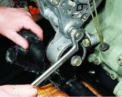
1. Loosen the nut of the generator lower mounting bolt to the front engine support and...
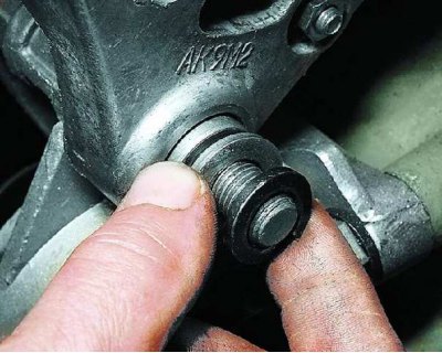
2....remove the spring and flat washers from the bolt.
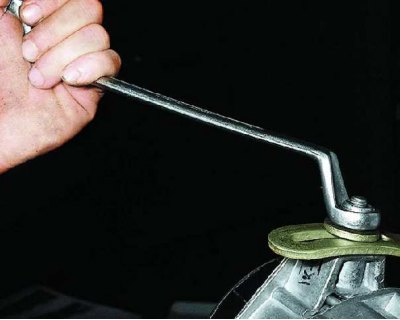
3. Loosen the nut securing the generator to the tension bar.
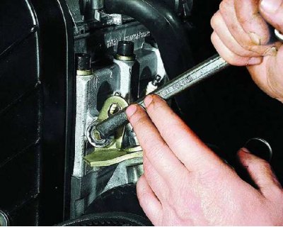
4. Loosen the nut securing the generator tension bar to the cylinder head stud.
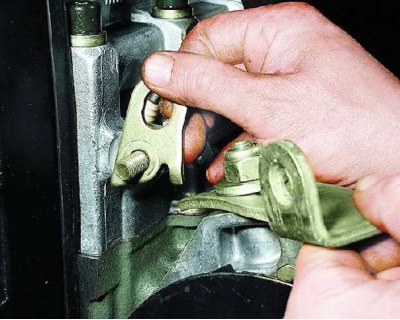
5. Remove the eye from the stud and the tension bar. Place the ring on the stud and screw on the nut (the eye will be needed to remove the engine from the subframe).
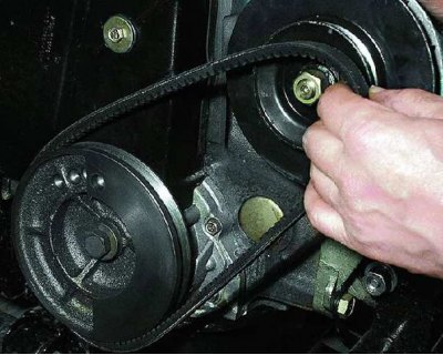
6. Remove the alternator drive belt from the alternator pulleys and engine crankshaft.
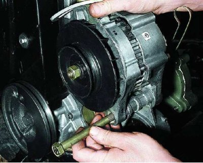
7. Remove the lower alternator mounting bolt from the front engine mount and remove the alternator together with the tension bar.
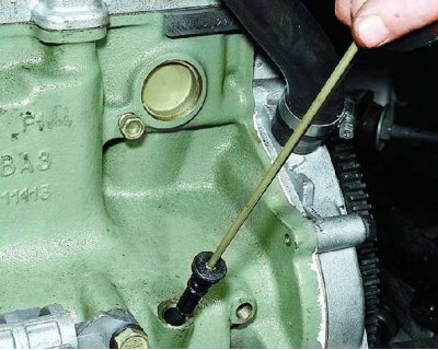
8. Remove the oil dipstick from the cylinder block hole.
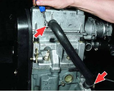
9. Loosen the clamps on the engine crankcase ventilation hose and remove the hose.
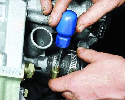
10. Loosen the clamp securing the connecting hose to the cylinder head outlet pipe and...
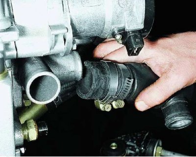
11....remove the hose from the branch pipe together with the thermostat.
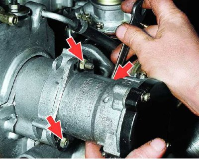
12. Loosen the three nuts securing the spark timing sensor to the auxiliary drive housing.
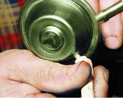
13. Disconnect the hose from the vacuum advance regulator and remove the spark timing sensor from the drive housing.
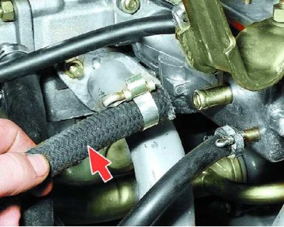
14. Loosen the clamps and disconnect the vacuum booster hoses and... from the intake pipe.
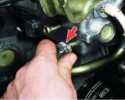
15....heating the intake pipe.
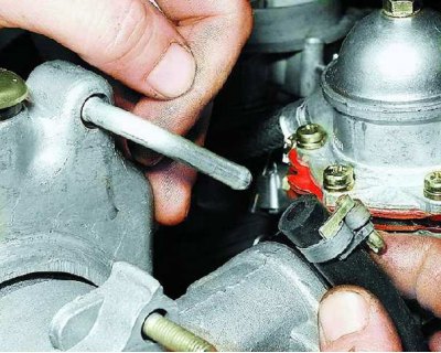
16. Loosen the clamp and disconnect the small branch crankcase ventilation hose from the cylinder head cover fitting.
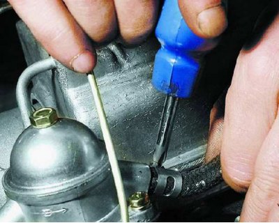
17. Loosen the fuel hose clamp (from fuel pump to carburetor) and...
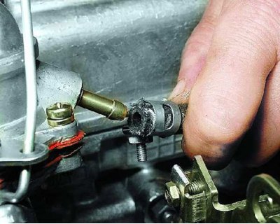
18....remove it from the fuel pump delivery nipple.
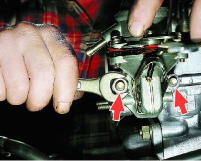
19. Unscrew the two fuel pump mounting nuts and...
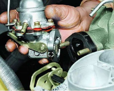
20....remove the fuel pump from the drive housing studs.
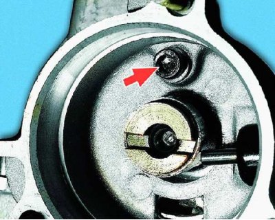
21. Loosen the auxiliary drive housing mounting bolt and...
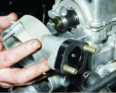
22....remove the drive housing from the cylinder head studs.
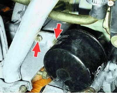
23. Remove the two bolts securing the intake pipe bracket (spring washers are installed under the bolts).
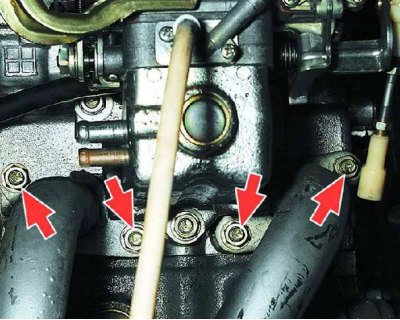
24. Unscrew the four nuts securing the flanges of the exhaust pipe to the studs of the cylinder head (flat washers are installed under the nuts) and...
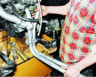
25....remove the intake pipe with the bracket and the warm air supply hose to the air filter.
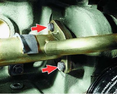
26. Unscrew the two bolts securing the water pump inlet pipe flange.
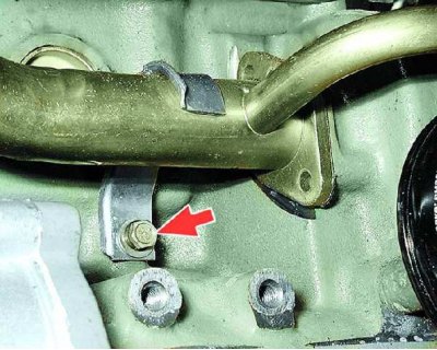
27. Loosen the bolt securing the supply pipe bracket to the cylinder block and...
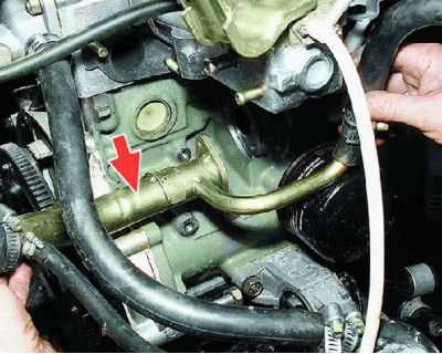
28....remove the water pump inlet pipe with hoses and thermostat assembly.
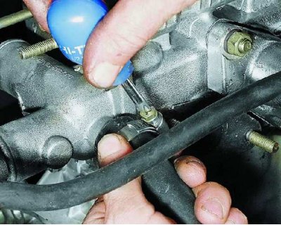
29. Loosen the clamp and remove the heater outlet hose from the cylinder head outlet pipe.
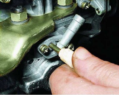
30. Disconnect the vacuum advance regulator hose from the carburetor fitting.
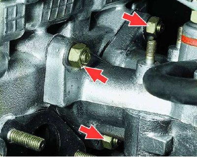
31. Remove the three nuts securing the intake pipe to the cylinder head (flat washers are installed under the nuts) and...
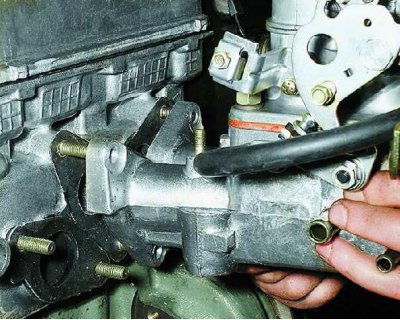
32....remove the intake pipe assembly with the carburetor.
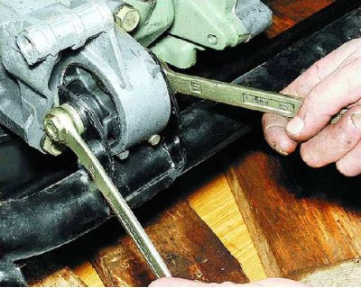
33. Attach the lifting gear straps to the engine frames. Raise the engine by tightening the straps. Loosen the nut on the bolt securing the front engine mount to the subframe bracket...
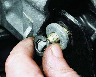
34....remove the spring and flat washers and...
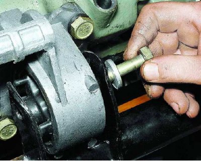
35....remove the bolt with the flat washer.
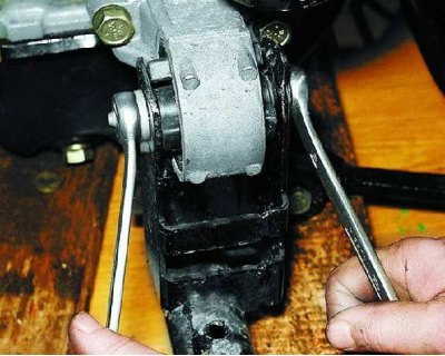
36. Loosen the nut securing the rear engine mount to the subframe, remove the spring and flat washers and...
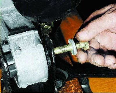
37....remove the bolt with the flat washer. Remove the engine from the subframe.
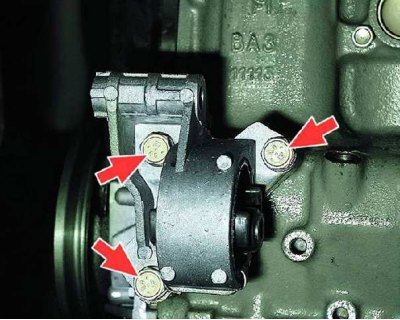
38. Place the engine on a stable stand or a disassembly and assembly stand. Remove the three bolts securing the front engine mount to the cylinder block and remove the mount.
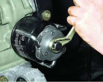
39. Remove the oil filter from the engine (we recommend using a special puller).
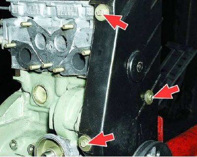
40. Loosen the three bolts securing the front camshaft drive belt cover and remove it.
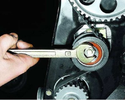
41. Loosen the tension roller mounting nut.
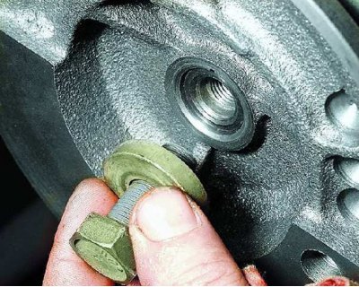
42. Loosen the generator drive pulley mounting bolt from the crankshaft, securing the flywheel from turning (place a screwdriver against the bolt that secures the clutch housing to the engine and against the flywheel ring gear). Remove the pulley mounting bolt with flat washer.
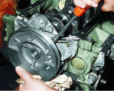
43. Carefully pry it up with a screwdriver (or a mounting blade) generator drive pulley and remove it from the front end of the crankshaft.
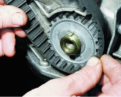
44. Remove the camshaft timing belt from the crankshaft pulley.
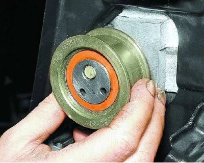
45. Remove the tension roller from the cylinder block stud.
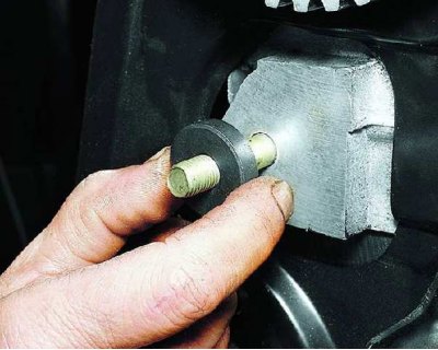
46. Remove the tension roller spacer ring.
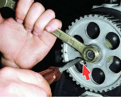
47. Secure the camshaft pulley from turning by placing a screwdriver against the timing belt cover mounting stud and unscrew the pulley mounting bolt.
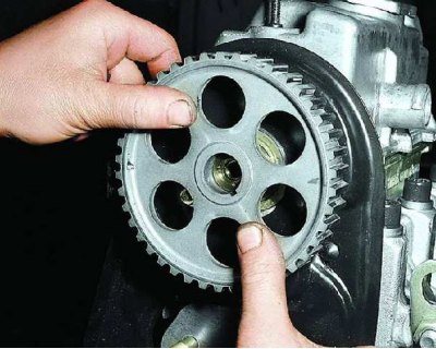
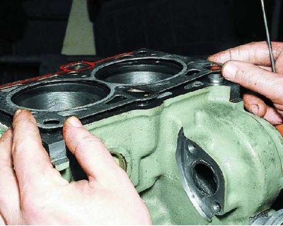
48. Remove the camshaft toothed pulley, remove the pulley key if it does not fit tightly in the shaft groove.
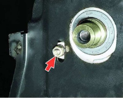
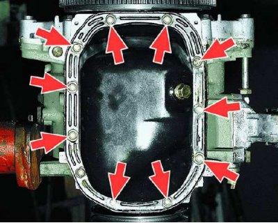
49. Unscrew the nut and...
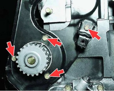
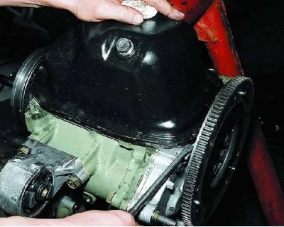
50....four bolts securing the rear cover (three of them attach the water pump to the cylinder block).
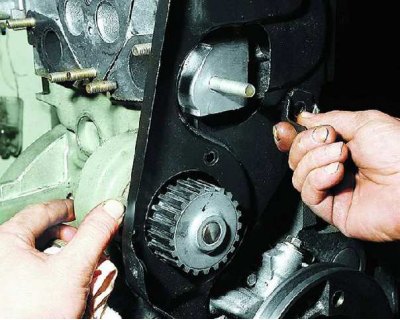
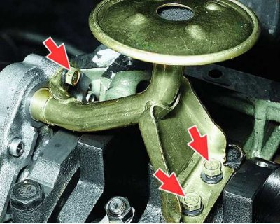
51. Remove the rear timing belt cover.
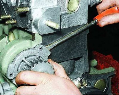
52. Insert a screwdriver between the pump housing flange and the block, slide the pump from its seat.
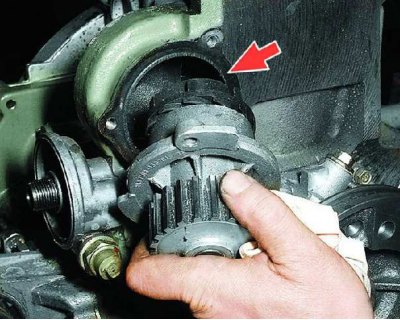
53. Remove the pump and gasket (shown by arrow).
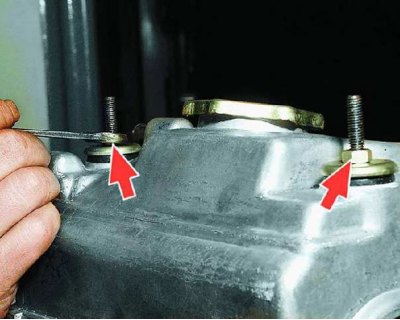
54. Unscrew the two nuts securing the cylinder head cover, remove the flat washers and...
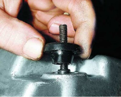
55....rubber bushings.
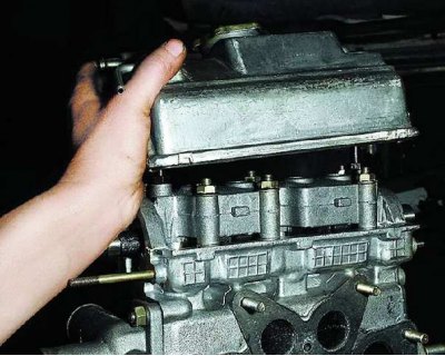
56. Remove the cylinder head cover.
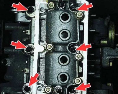
57. Remove the six cylinder head mounting bolts...
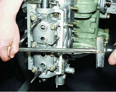
58....with a replacement head, hexagon socket bolt wrench and torque wrench (since the tightening torque of the bolts is about 80 N/m or 8 kgf/m).
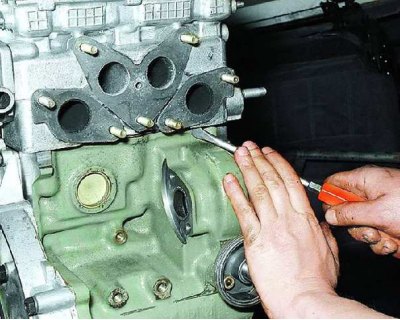
59. Using a screwdriver, separate the head from the block and...
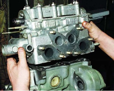
60....remove the cylinder head.
61. Remove the cylinder head gasket.
62. Remove the eleven bolts securing the engine oil pan.
63. Using a screwdriver, separate the oil pan from the cylinder block and remove the pan and its gasket.
64. Remove the three bolts securing the oil pump receiver (spring washers are installed under the bolt heads) and remove the receiver.
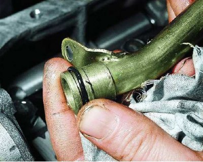
65. Remove the sealing ring from the oil pump receiver.
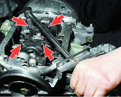
66. Unscrew the four nuts securing the lower connecting rod caps (two on each lid).
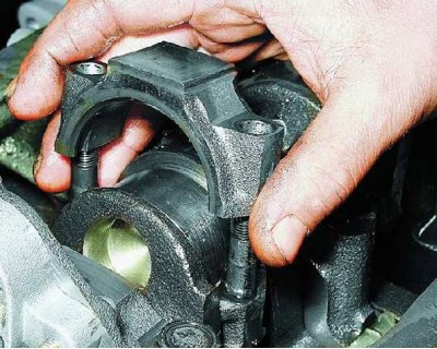
67. Remove the connecting rod bearing caps. If the cylinder numbers are not visible, mark them (by kerning or paint).
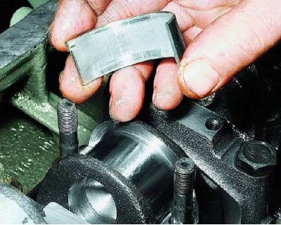
68. Remove the connecting rod bearing shells from the crankshaft journals. If you do not plan to replace the shells, mark them on the non-working side.
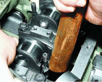
69. Carefully push the connecting rods into the cylinders so that the connecting rods do not touch the cylinder walls.
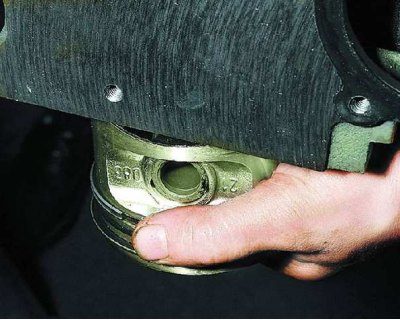
70. Remove the pistons with connecting rods as an assembly from the cylinders. If the cylinder numbers on the connecting rods are not visible, apply marks (by kerning or paint).
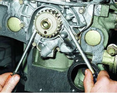
71. Use screwdrivers to pry up the crankshaft toothed pulley and...
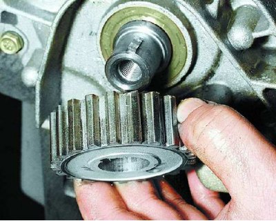
72....remove it from the front end of the crankshaft.
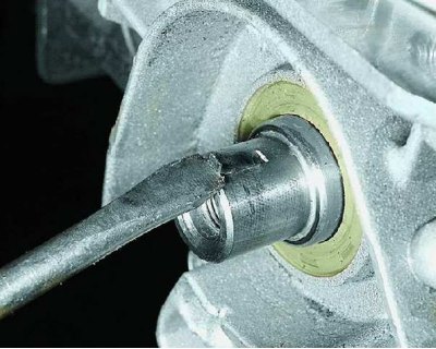
73. Remove the toothed pulley mounting key from the groove in the front end of the crankshaft.
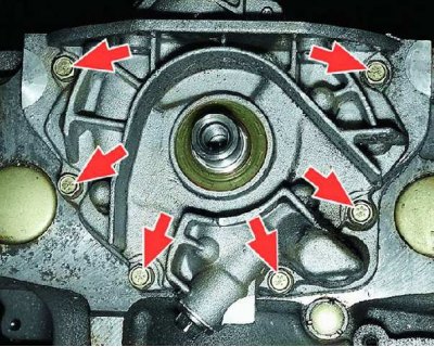
74. Remove the six oil pump mounting bolts...
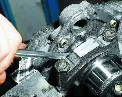
75....pry it up with a screwdriver and separate the pump from the cylinder block.
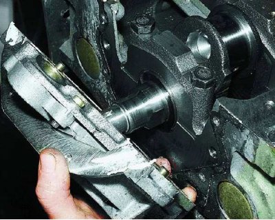
76. Remove the oil pump assembly from the front end of the crankshaft.
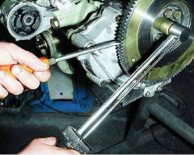
77. Secure the flywheel from turning, unscrew the six bolts that secure it and...
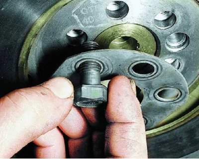
78....remove the bolt lock washer.
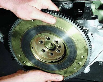
79. Remove the flywheel from the rear flange of the engine crankshaft.
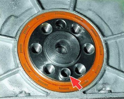
80. Please note: if the installation sleeve remains in the flywheel, immediately mark the hole in the crankshaft in which it was installed. Otherwise, an imbalance will occur.
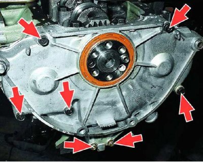
81. Remove the five bolts and two nuts securing the crankshaft rear oil seal holder.
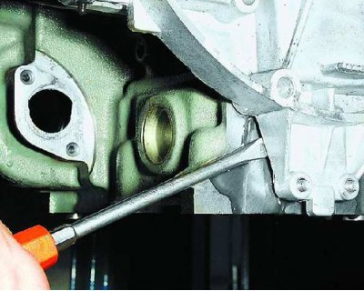
82. Pry the holder up with a screwdriver and...
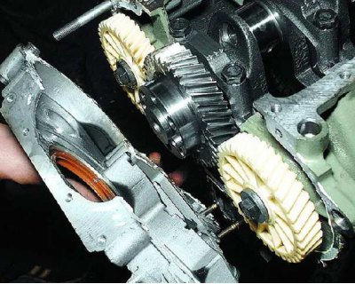
83....remove it from the engine.
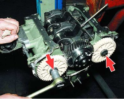
84. Secure the crankshaft from turning by inserting a metal rod or pin into the balancing hole of its counterweight and unscrew the bolts securing the balance shaft gears.
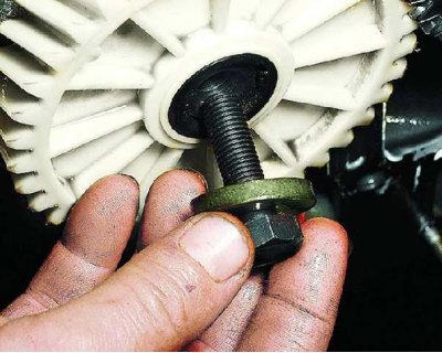
85. Remove the bolts with flat washers.
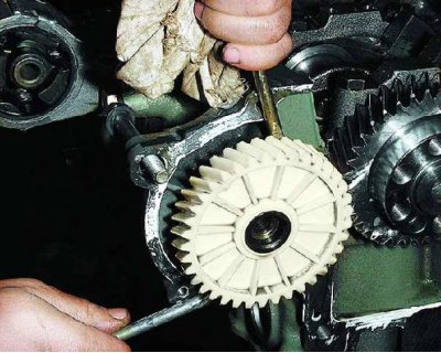
86. Pry up the balance shaft gears with two screwdrivers and...
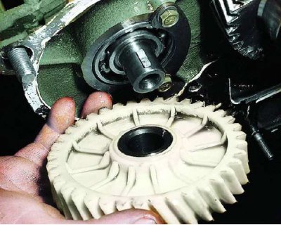
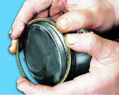
87....remove them from the shafts.
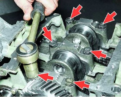
88. Remove the six crankshaft main bearing cap mounting bolts (two bolts on each cover) and...
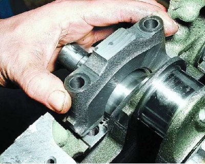
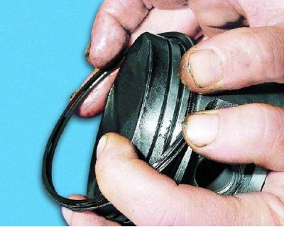
89....remove the main bearing caps and lower bearing shells.
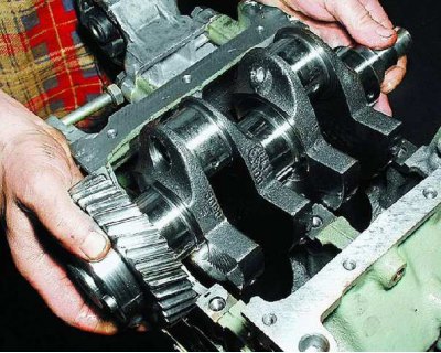
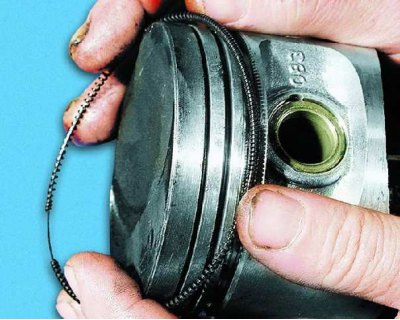
90. Remove the crankshaft from the cylinder block beds.
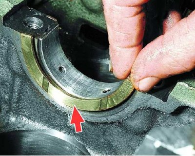
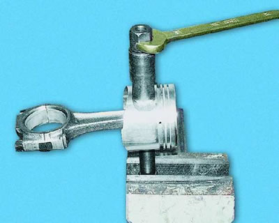
91. Remove the crankshaft thrust washers (on the middle main bearing of the crankshaft) and the upper main bearing shells.
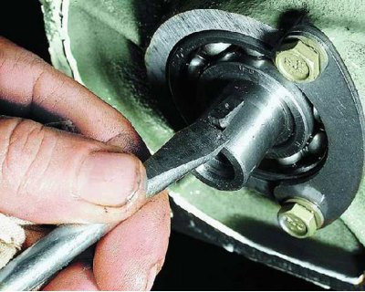
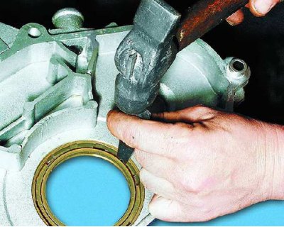
92. If necessary, remove the keys from the rear ends of the balance shafts.
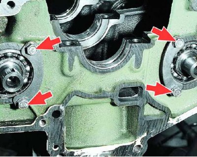
93. If it is necessary to replace the rear balance shaft bearings, unscrew the bolts securing the thrust plates and...
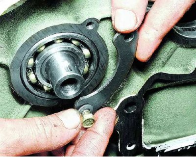
94....remove the plates.
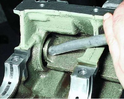
95. Knock the rear shaft bearings out of the cylinder block sockets by hitting the balance shafts with a soft metal drift and...
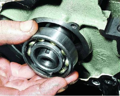
96....remove the rear balance shaft bearings.
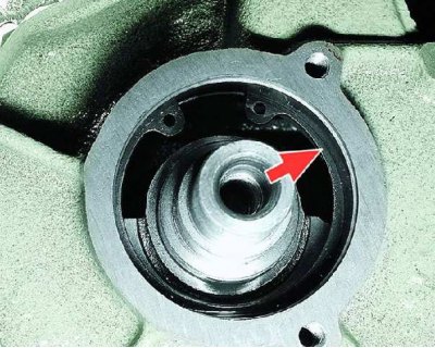
97. If the front bearings need to be replaced, remove the balance shafts. To do this, remove the rear bearing retaining rings using special pliers...
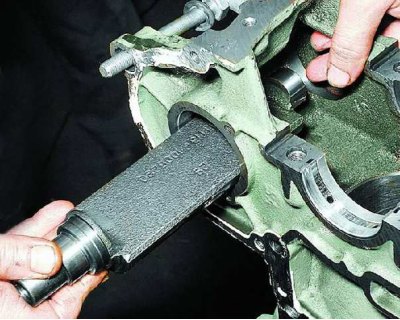
98.... remove the balance shafts from the cylinder block through the rear bearing seats...
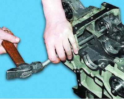
99....knock out the plugs of the front ends of the balance shafts, remove the retaining rings and press out the front bearings using a drift (punch), applying force to the outer rings of the bearings.
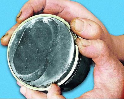
100. We recommend removing the piston rings with a special puller. If you don't have one, carefully loosen the lock of the upper compression ring and remove it from the piston.
101. Remove the lower compression ring in the same way...
102....oil scraper rings (upper and lower) and...
103....oil scraper ring expander.
104. If necessary, use a special mandrel to press the pin out of the connecting rod. Note that to assemble the piston with the connecting rod, it is necessary to heat the upper head of the connecting rod to a temperature of 240°C and a special mandrel is needed to install the piston pin.
105. Press the rear crankshaft oil seal out of the holder, placing blocks under the holder to avoid damaging it. Clean the mating surface of the holder to the cylinder block from any remaining old sealant.