
English Русский
Български
Беларускі
Український
Српски
Hrvatski
Română
Polski
Slovenský
Magyar
| Articles | Contacts | Sitemap |   
Repair and maintenance Lada Repair and maintenance Mazda Repair and maintenance Mitsubishi Repair and maintenance Toyota Repair and maintenance Land Rover Repair and maintenance Hyundai Repair and maintenance Nissan
VAZbook.ru


Main     1111   2101   2105   2106   2107   2109   2110   2115   2121  
VAZ-2114 (2004-2013) VAZ-2115 (1997-2012)
  • Main
  • «Samara-2»
  • VAZ-2115
  • Power unit
  • Engine repair
  • Disassembling the engine

Disassembling the engine (VAZ-2115)

            0

1. Remove the engine from the vehicle (see "Removal and installation the engine").

2. Place the engine on strong supports.

3. Carefully remove the gearbox (see "Removal and installation the gearbox" in the subsection "Transmission"). Make sure that the splined end of the input shaft does not rest on the petals of the diaphragm spring.

4. Remove the clutch from the engine (see "Clutch repair" in the subsection "Clutch").

5. Remove the camshaft drive belt, tension roller and spacer washer installed underneath it (see "Replacing the camshaft drive belt and adjusting the belt tension").

6. Remove the camshaft sprocket (see "Replacing the cylinder head gasket").

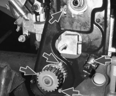
7. Remove four bolts (three of them also have a water pump attached) and the nut securing the rear cover of the camshaft drive belt, remove the cover.
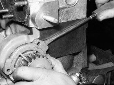
8. Insert a screwdriver between the pump housing flange and the block, slide the pump off its seat.…


8. Insert a screwdriver between the pump housing flange and the block, slide the pump off its seat. Remove the water pump.
9. Remove the head from the cylinder block (see «Replacing the cylinder head gasket»).


9. Remove the head from the cylinder block (see "Replacing the cylinder head gasket").


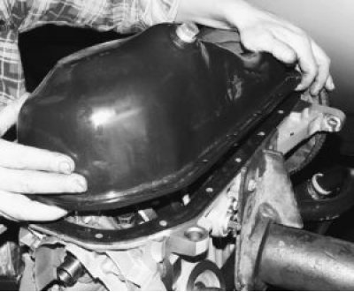
10. Unscrew the sixteen oil pan mounting bolts and remove it together with the gasket.
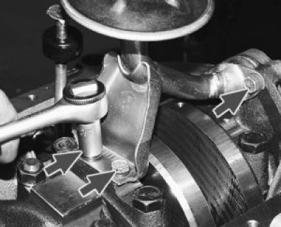
11. Remove the three oil receiver mounting bolts (spring washers are installed under the bolt…


11. Remove the three oil receiver mounting bolts (spring washers are installed under the bolt heads) and take it off.
12. Unscrew the bolt (a spring washer is installed under the bolt head) fastening the oil level…


12. Unscrew the bolt (a spring washer is installed under the bolt head) fastening the oil level sensor in the oil pan…
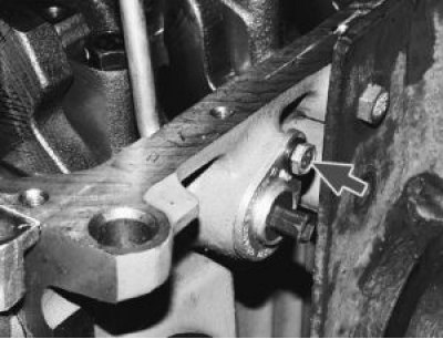
13. …and remove the sensor from the cylinder block. If necessary, turn the crankshaft so that the…


13. …and remove the sensor from the cylinder block. If necessary, turn the crankshaft so that the shaft counterweight does not interfere with removing the sensor.
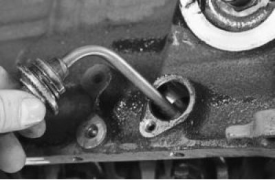

14. Turn the crankshaft so that the piston being removed is at the bottom dead center (BDC).…


14. Turn the crankshaft so that the piston being removed is at the bottom dead center (BDC). Unscrew the two connecting rod cap fastening nuts.
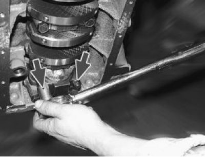
15. Remove the connecting rod cap. If the cap is difficult to remove, first knock it off with light…


15. Remove the connecting rod cap. If the cap is difficult to remove, first knock it off with light hammer blows. The cylinder number on the cap may not be visible, in which case mark the cap with the cylinder number.
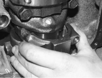
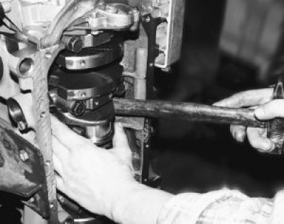
16. Push the connecting rod into the cylinder with the handle of the hammer and carefully remove…


16. Push the connecting rod into the cylinder with the handle of the hammer and carefully remove the piston with the connecting rod from the cylinder. In doing so, make sure that the lower head of the connecting rod does not touch the cylinder mirror, otherwise the mirror can be damaged. Remove the remaining pistons in the same way.
17. Remove the flywheel (see «Removal, installation and inspection of the flywheel»).


17. Remove the flywheel (see "Removal, installation and inspection of the flywheel").

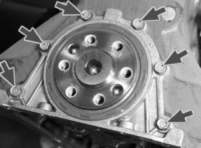
18. Remove six bolts (spring washers are installed under the bolt heads), remove the crankshaft rear oil seal retainer and gasket.
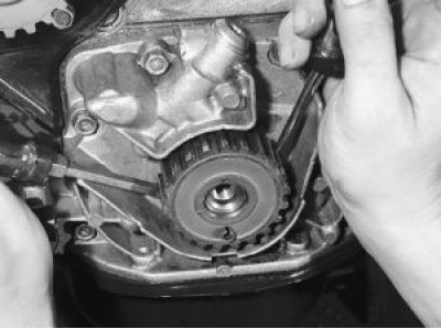
19. Remove the toothed pulley from the crankshaft. If the key does not fit tightly in the groove of…


19. Remove the toothed pulley from the crankshaft. If the key does not fit tightly in the groove of the crankshaft, remove it so as not to lose it.
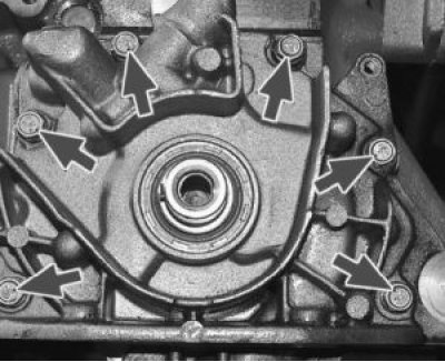
20. Remove six bolts (spring washers are installed under the bolt heads), remove the oil pump and…


20. Remove six bolts (spring washers are installed under the bolt heads), remove the oil pump and gasket.
21. Remove two bolts securing the five main bearing caps.
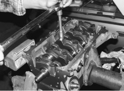

21. Remove two bolts securing the five main bearing caps.

22. Remove the covers.
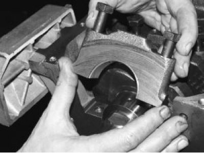

22. Remove the covers.

23. Remove the crankshaft.
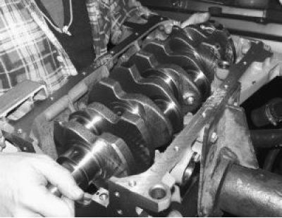

23. Remove the crankshaft.

24. Remove the crankshaft thrust half rings on the middle support.
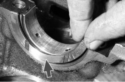

24. Remove the crankshaft thrust half rings on the middle support.

25. Remove the liners from the main bearing caps and from the block beds. If the liners are not to…


25. Remove the liners from the main bearing caps and from the block beds. If the liners are not to be replaced, as you remove them…
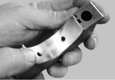
26. …mark the inserts on the non-working side relative to the covers and beds.
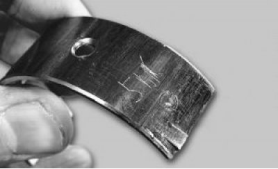

26. …mark the inserts on the non-working side relative to the covers and beds.

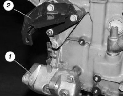
27. If it is necessary to remove the generator brackets 1 and engine mounts 2, unscrew the three…


27. If it is necessary to remove the generator brackets 1 and engine mounts 2, unscrew the three bolts securing them and the water pump supply pipe, unscrewing the two bolts securing it.
28. Remove the piston rings using a special puller. If you don't have one, remove the rings from…


28. Remove the piston rings using a special puller. If you don't have one, remove the rings from the piston by carefully spreading the ring locks.
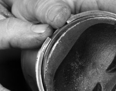
29. Remove the oil scraper ring expansion spring from the piston.
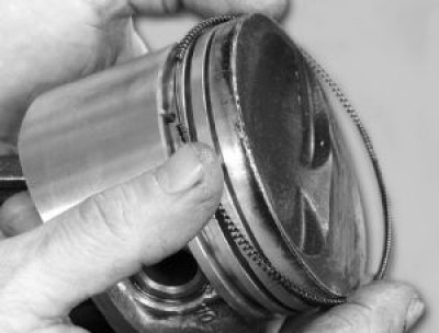

29. Remove the oil scraper ring expansion spring from the piston.

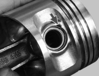
30. Remove the retaining rings holding the piston pin from both sides of the piston. The piston…


30. Remove the retaining rings holding the piston pin from both sides of the piston. The piston bosses have notches to facilitate ring removal.
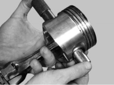
31. Using a suitable drift, push the pin out of the piston and remove the piston from the…


31. Using a suitable drift, push the pin out of the piston and remove the piston from the connecting rod.
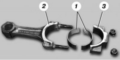
32. Remove liners 1 from connecting rod 2 and its cap 3. If the liners remain on the crankshaft,…


32. Remove liners 1 from connecting rod 2 and its cap 3. If the liners remain on the crankshaft, remove them from the shaft. If you do not intend to replace the liners, mark them on the non-working surface relative to the connecting rods and caps as you remove them.
32. Remove liners 1 from connecting rod 2 and its cap 3. If the liners remain on the crankshaft,…


This article is available at russian, bulgarian, belarusian, ukrainian, serbian, croatian, romanian, polish, slovak, hungarian
The text was reviewed by the specialist: Grigory Vologodtsev

Share with friends:

Previous articles
VAZ-2115: Engine repair
Next articles

Engine installation
Removal the engine
Adjusting valve clearances
Lapping valves
Cylinder head repair
Engine defect detection
Engine assembly
Removal and installation the oil pump
Oil pump repair
Flushing of crankcase ventilation system components

More articles from other manuals on VAZ cars:
➠ Disassembling the engine VAZ-11113 (1996-2003)
➠ Disassembling the engine VAZ-2101 (1970-1983)
➠ Disassembling the engine VAZ-2105 (1979-2010)
➠ Disassembling the engine VAZ-21213 (1994-2006)
➠ The engine structure of VAZ-2106 and VAZ-2103 cars VAZ-2106 (1976-2006)
Link in different formats to this page


Visitor comments

No comments yet


How much will 28 + 43 ?


VAZ-2114 (2004-2013) 
  • General information
  • Operation and maintenance
  • Power unit
  • Engine repair
  • Cooling system
  • Supply system
  • Control system
  • Exhaust system
  • Transmission
  • Clutch
  • Car gearbox
  • Front wheel drives
  • Chassis
  • Wheels and tires
  • Front suspension
  • Rear suspension
  • Steering
  • Brake system
  • Body
  • Exterior
  • Interior
  • Doors and glass
  • Tailgate
  • Ventilation and heating
  • Electrical equipment
  • Equipment and devices
  • Headlights and lighting
  • Engine electrics
  • Electrical circuits


VAZ-2115 (1997-2012) 
  • General information
  • Vehicle device
  • Operation manual
  • Vehicle malfunctions
  • Car care
  • Power unit
  • Engine repair
  • Cooling system
  • Supply system
  • Control system
  • Exhaust system
  • Transmission
  • Clutch
  • Car gearbox
  • Front wheel drives
  • Chassis
  • Front suspension
  • Rear suspension
  • Steering
  • Brake system
  • Body
  • Exterior
  • Interior
  • Doors, covers and windows
  • Electrical equipment
  • Equipment and devices
  • Headlights and lighting
  • Engine electrics
  • Anti-theft system


VAZbook.ru © 2017 · Mobile version · Contact with administration · Sitemap: EN BG BY UA RS HR RO PL SK HU · Site search · News and articles VAZ-1111 · VAZ-11113 · VAZ-2101 · VAZ-21011 · VAZ-2104 · VAZ-2105 · VAZ-21051 · VAZ-2106 · VAZ-21061 · VAZ-2107 · VAZ-21099 · VAZ-2109 · VAZ-2108 · VAZ-2110 · VAZ-2112 · VAZ-2114 · VAZ-2115 · VAZ-2121 · VAZ-21213 · VAZ-21214 ·
The site stores technical data using cookies to improve the service.