
Removing the bipod
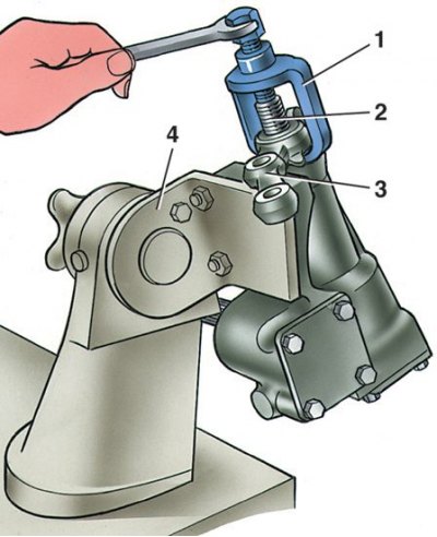
1 - puller A.47043; 2 – a shaft of a bipod of a steering; 3 - bipod; 4 - bracket А.74076/R
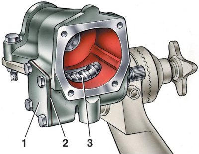
Steering Gear Parts
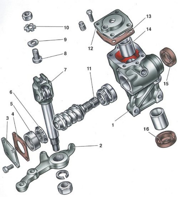
1 - crankcase; 2 - bipod; 3 - lower crankcase cover; 4 - adjusting shims; 5 - the outer ring of the worm shaft bearing; 6 - separator with balls; 7 - bipod shaft; 8 - adjusting screw; 9 - adjusting plate; 10 - lock washer; 11 - worm shaft; 12 - top cover of the crankcase; 13 - sealing gasket; 14 - bipod shaft sleeve; 15 - worm shaft seal; 16 - bipod shaft seal
Control of the friction moment of the worm with a dynamometer
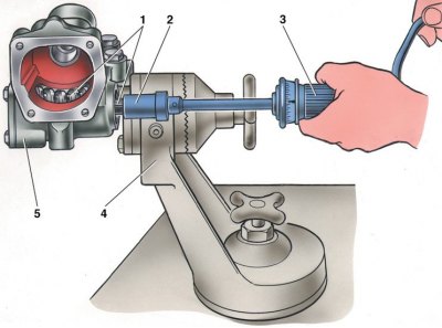
1 - worm; 2 – head А.95697/5; 3 – dynamometer 02.7812.9501; 4 - stand bracket for repairing the crankcase of the steering gear; 5 - steering gear housing
Disassembly
1. Drain the oil from the steering box. Fasten the crankcase to bracket A.74076/R with support A.74076/1.
2. Having unscrewed the nut of fastening of the steering arm 2 (see fig. Steering Gear Parts) and removing the spring washer, remove the bipod with a puller A.47043 (see fig. Removing the bipod).
3. Having unscrewed the fastening bolts, remove the cover 12 (see fig. Steering Gear Parts) steering gear housing together with adjusting screw 8, adjusting plate 9, lock washer 10 and locknut.
4. Remove from the crankcase 1 shaft 7 of the bipod assembly with the roller.
5. Having unscrewed the fastening bolts, remove the cover 3 of the worm shaft thrust bearing together with the shims 4.
6. Using the shaft 11 of the worm, push the outer ring 5 of the bearing out of the crankcase and remove the shaft together with the separators 6 of the bearings.
7. Remove the worm shaft seal 15 and the bipod shaft seal 16.
8. Tool 3 (mandrel 67.7853.9541) press out the outer ring of the upper bearing 2 (1 - steering gear housing).
Assembly
1. Assemble the steering mechanism on the bracket A.74076/R in the reverse order of disassembly.
2. Press the outer ring of the upper bearing of the worm with mandrel 67.7853.9541, rearranging the nozzle on the handle of the mandrel with the reverse side.
3. After installing the worm in the steering gear housing and fixing the bottom cover, check with a dynamometer 02.7812.9501 and head A.95697/5 (see fig. Control of the friction moment of the worm with a dynamometer) moment of friction of the worm shaft; it should be in the range of 19.6–49 N cm (2–5 kgf cm).
4. If the torque is less than specified, reduce the thickness of the shims 2; if more, increase (1 - bearing cover; 3 - worm).
5. After installing the bipod shaft, check the absence of play in the engagement of the roller with the worm in the positions of the worm shaft turned to the right and left by 30°from the neutral position of the bipod.
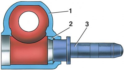
6. Eliminate any gap in the engagement with the adjusting screw 2 (see fig. Section of the crankcase of the steering mechanism) and tighten locknut 3.
7. After adjusting the gap in the meshing of the roller and the worm, check the moment of friction of the worm shaft with a dynamometer, which should be equal to 88.2–117.8 N cm (9–12 kgf cm) when turning the worm shaft by 30°both to the left and to the right from the middle position and should decrease smoothly to 68.6 N cm (7 kgf cm) when turning from an angle of 30°to the stop.
8. Upon completion of assembly, check the angles of rotation of the bipod from the neutral position, which should be 32°10'±1°both to the left and to the right until the bipod stops against the bolt heads, pour 0.215 liters of TAD-17i gear oil into the steering gear housing.