
English Русский
Български
Беларускі
Український
Српски
Hrvatski
Română
Polski
Slovenský
Magyar
| Articles | Contacts | Sitemap |   
Repair and maintenance Lada Repair and maintenance Mazda Repair and maintenance Mitsubishi Repair and maintenance Toyota Repair and maintenance Land Rover Repair and maintenance Hyundai Repair and maintenance Nissan
VAZbook.ru


Main     1111   2101   2105   2106   2107   2109   2110   2115   2121  
VAZ-1111 (1988-1996) VAZ-11113 (1996-2003)
  • Main
  • «Oka»
  • VAZ-1111
  • Chassis
  • Steering
  • Steering gear assembly

Steering gear assembly (VAZ-1111)

            0

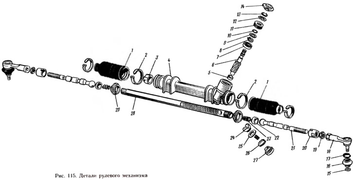
Before assembly, pay special attention to ensure that no chips or other foreign bodies get into the steering gear housing. Using mandrel 67.7853.9594 (inner diameter 18 mm, outer diameter 22 mm), press on ball bearing 7 (see figure 115) onto the shaft of the drive gear 6 until it stops. Using mandrel 41.7853.4006, install the retaining ring 8 onto the shaft of the gear, preventing it from becoming skewed, then install the protective washer 9 and sealing ring 10.

Before assembly, pay special attention to ensure that no chips or other foreign bodies get into the…


Install support bushing 3 into the crankcase, making sure that its projections enter the crankcase openings. If it is necessary to replace roller bearing 5, press it in under a press using mandrel 67.7853.9585.

Having generously lubricated the rack teeth with FIOL-1 grease and its other surfaces with a thin layer of the same grease, install the rack in the housing 4, pushing it through the support sleeve 3 until it stops in a special device in order to maintain the size of (115±0.25) mm between the center of the drive gear and the outer end of the rod stop.

Apply FIOL-1 grease to the teeth of the drive gear and place it in the ball bearing until it appears on the upper end of the bearing. Then install the gear assembly with the bearing in the crankcase. The maximum bearing pressing force is 1500 N. The total amount of grease for the rack, drive gear and bearing should be 20-30 g.


Using key 67.7812.9536, tighten the drive gear nut to a torque of (50±5) Nm, install protective washer 9 (see figure 115) and fill the cavity above the nut with UNIOL-1 grease.

The drive gear is set to the position of straight-line movement of the vehicle [determined by the size (115±0.25) mm, see figure 114].

Install the 24 rail stop (see figure 115) with sealing ring 25 until it stops in the rack (to a gap-free state). Install the retaining ring 26, the stop spring and tighten the new nut 27 with the key 67.7812.9537 to a torque of 11-13 N·m, then loosen the nut by 2 divisions (24°) to ensure a gap of up to 0.12 mm between the nut and the rack stop, necessary to compensate for the thermal expansion of the parts and manufacturing tolerances for their manufacture. The torque for unscrewing the nut must be at least 4.51 N·m. Then use the mandrel 67.7853.95861 press the dust cover 14 onto the gear shaft (see figure 115) so that marks A and B (see figure 113) on the boot and on the crankcase match, and the boot fits tightly against the end of the crankcase. After this, make sure that the gear rotation torque in the area of the entire stroke is within 60-170 N cm at a rotation speed of 30 min⁻¹. If the gear rotation torque does not fit within the specified limits, identify and eliminate the causes of jamming of the parts, paying special attention to the rack stop, drive gear and rack. Then punch nut 27 (see figure 115) stop at two new opposite points by pressing the thread of the housing without affecting the nut. The position of the nut is marked with paint to control the position of the nut.


Assemble the inner joint of the tie rod end, tightening the ball joint 20 with a torque that ensures free movement of the ball head of the tie rod in the support without axial clearance. In this position, tighten the lock nut 29 with a torque of 78.5-88.3 N·m and press the lock nut belts into the grooves of the support and rack. When assembling the inner joints, put 10 g of SHRUS-4 grease into the cavities of the supports for each support.

After assembly, make sure that there are no swellings or pinches on the protective covers 1 when the gear rotates at a frequency of 30 min⁻¹, and the gear rotation torque (at the same frequency) in the area of the entire stroke is within 60-170 N cm (6.1-17.33 kgf cm). Otherwise, the causes of the identified defects are eliminated.

The gear rotation torque is checked using a dynamometer 02.7812.9501 with an adapter sleeve 67.7812.9540.

If the outer ends 18 of the rods were removed, screw them onto the inner ends 21 and secure with locknuts 19.

Notes


1. Tubular mandrel ∅ 18 mm.


This article is available at russian, bulgarian, belarusian, ukrainian, serbian, croatian, romanian, polish, slovak, hungarian
The text was reviewed by the specialist: Grigory Vologodtsev

Share with friends:

Previous articles
VAZ-1111: Steering
Next articles

Checking the technical condition of the steering mechanism
Disassembling the steering mechanism
Checking the gap between the rack stop and the nut
Removal and installation steering
Checking the steering on a car

More articles from other manuals on VAZ cars:
➠ Removal and installation the steering gear VAZ-2101 (1970-1983)
➠ Checking and repairing steering gear parts VAZ-2105 (1979-2010)
➠ Steering gear engagement — adjustment VAZ-2106 (1976-2006)
➠ Steering gear engagement — adjustment VAZ-2107 (1982-2012)
➠ Steering gear assembly VAZ-2108 (1984-2003)
Link in different formats to this page


Visitor comments

No comments yet


How much will 16 + 43 ?


VAZ-1111 (1988-1996) 
  • General information
  • Vehicle description
  • Vehicle device
  • Vehicle operation
  • Maintenance
  • Applications
  • Power unit
  • Engine repair
  • Cooling system
  • Lubrication system
  • Supply system
  • Transmission
  • Clutch
  • Transmission
  • Chassis
  • Front suspension and wheels
  • Rear suspension
  • Steering
  • Brake system
  • Body
  • Exterior
  • Interior
  • Electrical equipment
  • Engine electrics
  • Equipment and devices


VAZ-11113 (1996-2003) 
  • General information
  • Introduction to the guide
  • User manual
  • Maintenance
  • Power unit
  • Engine repair
  • Cooling and lubrication system
  • Fuel system
  • Exhaust system
  • Transmission
  • Car gearbox
  • Clutch and drive shafts
  • Chassis
  • Front suspension
  • Rear suspension
  • Steering
  • Brake system
  • Body
  • Exterior
  • Interior
  • Doors and locks
  • Electrical equipment
  • Equipment and devices
  • Lighting and signaling
  • Engine electrics
  • Ignition system


VAZbook.ru © 2017 · Mobile version · Contact with administration · Sitemap: EN BG BY UA RS HR RO PL SK HU · Site search · News and articles VAZ-1111 · VAZ-11113 · VAZ-2101 · VAZ-21011 · VAZ-2104 · VAZ-2105 · VAZ-21051 · VAZ-2106 · VAZ-21061 · VAZ-2107 · VAZ-21099 · VAZ-2109 · VAZ-2108 · VAZ-2110 · VAZ-2112 · VAZ-2114 · VAZ-2115 · VAZ-2121 · VAZ-21213 · VAZ-21214 ·
The site stores technical data using cookies to improve the service.