
Generator parts 37.3701
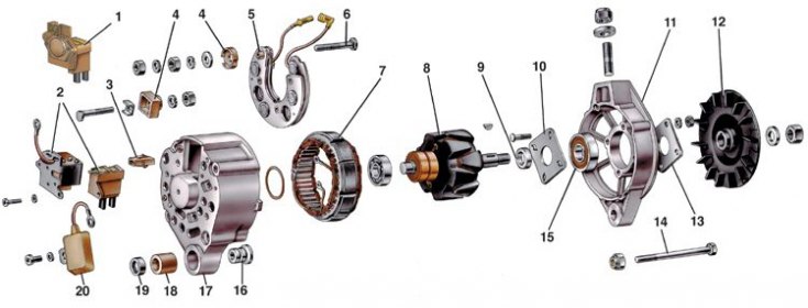
1 - voltage regulator assembly with brush holder for generators produced since 1996; 2 - voltage regulator and brush holder for generators manufactured before 1996; 3 - block output of additional diodes; 4 - insulating bushings; 5 - rectifier block; 6 - contact bolt; 7 - stator; 8 - rotor; 9 - remote bushing; 10 – internal washer of fastening of the bearing; 11 - cover from the drive side; 12 - pulley; 13 – an external washer of fastening of the bearing; 14 - coupling bolt; 15 - front ball bearing of the rotor; 16 - bushing; 17 - cover from the side of slip rings; 18 - buffer sleeve; 19 - clamping sleeve; 20 - capacitor
Details of the front of the G-222 generator
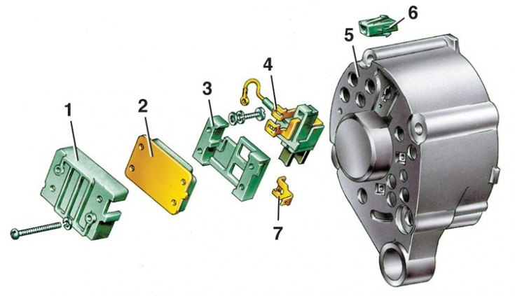
1 - casing; 2 - voltage regulator; 3 - base; 4 - brush holder with brushes; 5 - cover of the generator from the side of slip rings; 6 - block of the plug of the central output of the stator winding; 7 - output "15" generator (conclusion "B" voltage regulator)
Tool 67.7823.9504 includes a conventional puller and gripper. The latter consists of two steel half rings, which are inserted into the pulley stream. The half rings have the same section as the alternator drive belt. On the one hand, they are hinged, and on the other, they are equipped with levers that are compressed with one hand when removing the pulley.
Generator 37.3701
1. Clean and blow out the generator with compressed air.
2. Lock the alternator pulley with the grip included in the tool kit 67.7823.9504, unscrew the pulley fastening nut and press the pulley with a puller. Remove the pulley key and taper washer.
3. Disconnect the wire from the plug «IN» voltage regulator.
4. Disconnect the regulator and capacitor wires from the terminal "30" generator and unscrew the screws securing the voltage regulator.
5. For alternators manufactured before 1996, in order not to break the brushes when removing the brush holder, insert a screwdriver blade between the regulator housing 2 (see fig. Generator parts 37.3701) and brush holder, and partially slide the regulator out of the generator, leaving the brush holder in place.
6. After that, tilt and remove the regulator together with the brush holder from the generator. Remove the capacitor 20 by unscrewing the fastening screw.
7. Unscrew the nuts of the coupling bolts 14 and remove the cover 11 of the generator and the rotor 8. Unscrew the nuts of the screws connecting the tips of the diodes to the terminals of the stator winding and remove the stator 7 from the cover 17 of the generator.
8. Unscrew the nut of the contact bolt 6, disconnect the plug of the wire of additional diodes from the block 3 and remove the rectifier unit 5.
Generator G-222
1. The G-222 generator is disassembled in the same order. To remove the voltage regulator, unscrew the fastening screws and remove the cover 1 (see fig. Details of the front of the G-222 generator) assembled with regulator 2, base 3 and brush holder 4.
2. Then, unscrewing the screws, separate the regulator, base and brush holder with brushes.
3. Further disassembly of the G-222 generator is similar to the disassembly of the generator 37.3701.