
Connection diagram for testing the generator 37.3701 on the bench
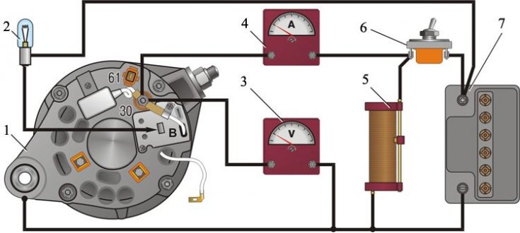
1 - generator; 2 - control lamp 12 V, 3 W; 3 - voltmeter; 4 - ammeter; 5 - rheostat; 6 - switch; 7 - battery
Attention! "Minus" battery must always be connected to ground, and "plus" - connect to clamp «30» generator. An erroneous reverse connection of the battery will immediately cause an increased current through the diodes of the rectifier block of the generator and they will be damaged.
Attention! The generator must not be operated with the battery disconnected. This causes the occurrence of pulses of increased voltage on the clamp "30" generator, which can damage the generator voltage regulator and electronic devices in the vehicle's on-board network.
Attention! It is forbidden to check the operability of the generator "for a spark" even short-term clamp connection "30" mass generator. In this case, a significant current flows through the valves and they are damaged. You can only check the generator with an ammeter and a voltmeter.
Attention! It is not allowed to check the diodes of the rectifier unit of the generator with a voltage of more than 12 V or with a megohmmeter, since it has a voltage too high for the diodes and they will be broken during the test (a short circuit will occur).
Attention! It is forbidden to check the car's electrical wiring with a megohmmeter or a lamp powered by a voltage of more than 12 V. If such a check is necessary, then first disconnect the wires from the generator.
Attention! It is necessary to check the insulation resistance of the stator winding with increased voltage only at the stand and always with the leads of the phase windings disconnected from the rectifier unit.
Attention! When welding components and parts of the car body, disconnect the wires from all terminals of the generator and the battery.
Testing on the bench allows you to determine the health of the generator and the compliance of its characteristics with the nominal ones. For the generator under test, the brushes must be well ground to the slip rings of the collector, and the rings themselves must be clean.
1. Install the generator on the stand and make the connections as shown in the diagram. Generator G-222 has a plug "15" connected directly to the output "30" generator.
2. Turn on the electric motor of the stand, set the generator output voltage to 13 V with rheostat 5 and bring the rotor speed to 5000 min–1.
3. Let the generator run in this mode for at least 10 minutes, and then measure the recoil current. For a working generator, it must be at least 55 A (45 A at the G-222 generator).
4. If the measured value of the output current is less, then this indicates a malfunction in the stator and rotor windings, damage to the diodes of the rectifier unit. In this case, a thorough check of the windings and diodes is necessary to determine the location of the fault.
5. The voltage at the generator output is checked at a rotor speed of 5000 min–1. Using rheostat 5, set the output current to 15 A and measure the voltage at the generator output, which should be 14.1±0.5 V at an ambient air temperature and a generator of 25±10°C.
6. If the voltage is not within the specified limits, replace the voltage regulator with a new known-good voltage regulator and recheck.
7. If the voltage is normal, then the old voltage regulator is damaged and must be replaced. And if the voltage still does not fit into the above limits, then it is necessary to check the windings and diodes of the generator.