
English Русский
Български
Беларускі
Український
Српски
Hrvatski
Română
Polski
Slovenský
Magyar
| Articles | Contacts | Sitemap |   
Repair and maintenance Lada Repair and maintenance Mazda Repair and maintenance Mitsubishi Repair and maintenance Toyota Repair and maintenance Land Rover Repair and maintenance Hyundai Repair and maintenance Nissan
VAZbook.ru


Main     1111   2101   2105   2106   2107   2109   2110   2115   2121  
VAZ-2108 (1984-2003) VAZ-2109 (1984-1997) VAZ-21099 (1990-2004)
  • Main
  • «Sputnik»
  • VAZ-21099
  • Electrical equipment
  • Engine electrics
  • Disassembling the generator

Disassembling the generator (VAZ-21099)

            0

Disassembling the generator


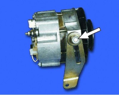
1. Loosen the nut and remove the adjusting bar.
1. Loosen the nut and remove the adjusting bar.


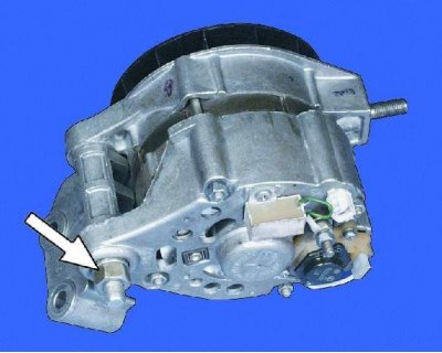
2. Unscrew the fastening nut and remove the pressure sleeve.
2. Unscrew the fastening nut and remove the pressure sleeve.


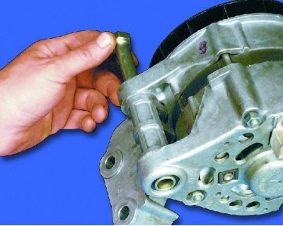
3. Remove the bolt and remove the bracket from the generator.
3. Remove the bolt and remove the bracket from the generator.


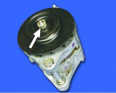
4. Loosen the mounting nut while holding the pulley from turning (see note), and remove the pulley together with the fan impeller. Remove the woodruff key from the armature shaft.


4. Loosen the mounting nut while holding the pulley from turning (see note), and remove the pulley…


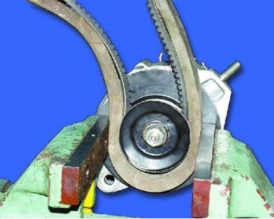
Note: The manufacturer recommends holding the pulley from turning with a special device. If you don't have a device, you can do it this way:


1. Put the alternator belt on the pulley and put another belt of a larger cross-section on top of it so as not to crush the pulley.

2. Clamp the pulley with belts in a vice and unscrew the fastening nut.
2. Clamp the pulley with belts in a vice and unscrew the fastening nut.


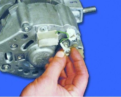
5. Unscrew the nut and disconnect the capacitor wire from terminal "30" of the generator.
5. Unscrew the nut and disconnect the capacitor wire from terminal «30» of the generator.


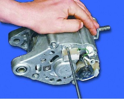
6. Loosen the screw and remove the capacitor.
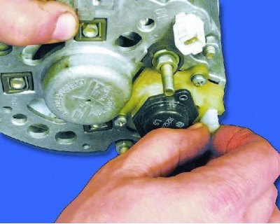

6. Loosen the screw and remove the capacitor.


7. Disconnect the connector with the wire from the brush holder.
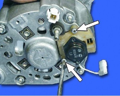
7. Disconnect the connector with the wire from the brush holder.


8. Remove the two screws securing the brush holder.
8. Remove the two screws securing the brush holder.


9. Remove the brush holder with the voltage regulator.
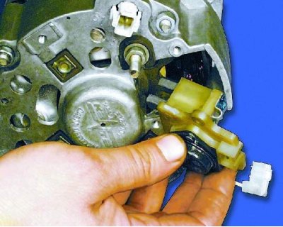
9. Remove the brush holder with the voltage regulator.


10. Unscrew the four mounting nuts...
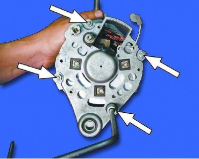
10. Unscrew the four mounting nuts...


11....and remove the four tie bolts.
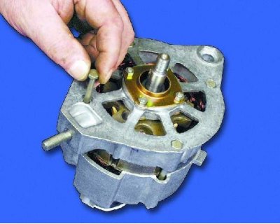
11....and remove the four tie bolts.


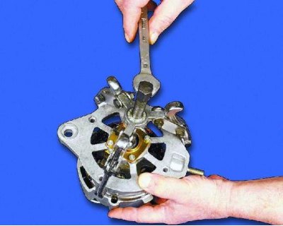
12. Using a puller, remove the cover from the drive side of the armature shaft.
12. Using a puller, remove the cover from the drive side of the armature shaft.


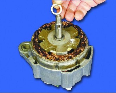
13. Remove the spacer sleeve from the armature shaft.
13. Remove the spacer sleeve from the armature shaft.


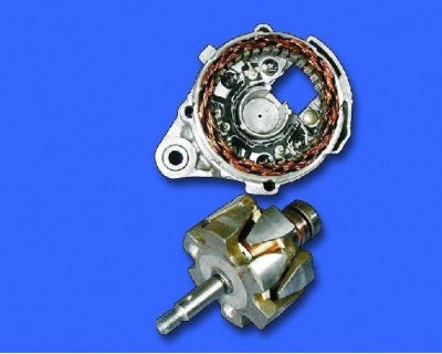
14. Remove the anchor from the manifold side cover.
14. Remove the anchor from the manifold side cover.


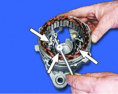
15. Unscrew the three fastening nuts and disconnect the stator terminals from the rectifier unit.
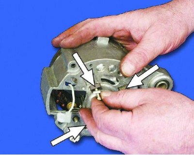
15. Unscrew the three fastening nuts and disconnect the stator terminals from the rectifier unit.


16. Remove the three bolts securing the rectifier block and the stator terminals with insulating pads.
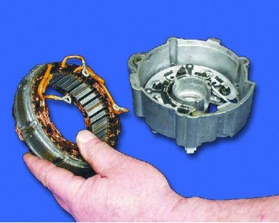
16. Remove the three bolts securing the rectifier block and the stator terminals with insulating…


17. Remove the stator from the cover.
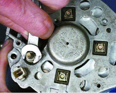
17. Remove the stator from the cover.


18. Unscrew the nut securing terminal "30".
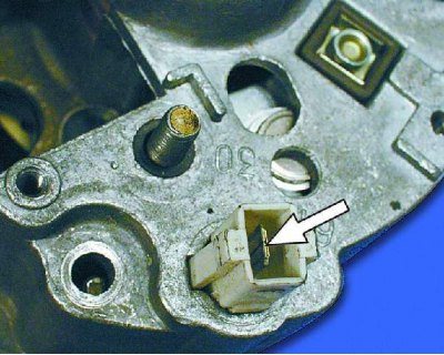
18. Unscrew the nut securing terminal «30».


19. Press the lug on the plug inside the block with a screwdriver and push the plug with the wire inside the cover. The plastic block remains on the cover.
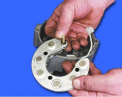
19. Press the lug on the plug inside the block with a screwdriver and push the plug with the wire…


20. Remove the rectifier unit from the cover.
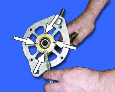
20. Remove the rectifier unit from the cover.


21. To replace the bearing in the cover on the drive side, unscrew the four mounting nuts, remove the bolts...
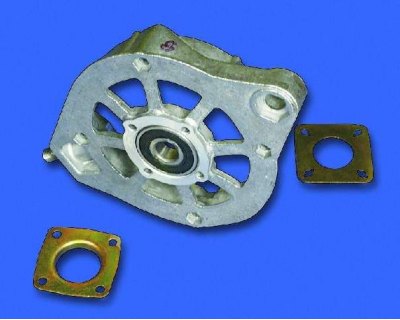
21. To replace the bearing in the cover on the drive side, unscrew the four mounting nuts, remove…


22....and remove the inner and outer bearing mounting washers. Then, using a suitable mandrel, press the bearing out of the cover. Press the new bearing flush with the cover surface. Apply force only to the outer bearing ring.
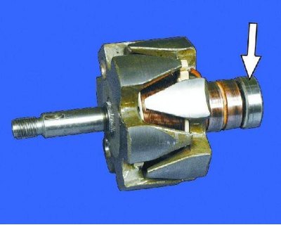
22....and remove the inner and outer bearing mounting washers. Then, using a suitable mandrel,…


23. To replace the bearing on the commutator side, press it off the armature shaft with a puller. Press the new bearing until it stops, applying force only to the inner bearing race.


This article is available at russian, bulgarian, belarusian, ukrainian, serbian, croatian, romanian, polish, slovak, hungarian
The text was reviewed by the specialist: Grigory Vologodtsev

Share with friends:

Previous articles
VAZ-21099: Engine electrics
Next articles

Removal the generator
Generator — General Information
Generator defect detection
Generator assembly
Starter — General Information
Removal and installation the starter
Disassembling the starter

More articles from other manuals on VAZ cars:
➠ Disassembling the generator VAZ-21011 (1974-1983)
➠ Disassembling the generator VAZ-21051 (1979-2010)
➠ Disassembling the generator VAZ-21213 (1994-2006)
➠ Disassembling the engine VAZ-1111 (1988-1996)
➠ The generator device of VAZ-2106 and VAZ-2103 cars VAZ-2106 (1976-2006)
Link in different formats to this page


Visitor comments

No comments yet


How much will 17 + 43 ?


VAZ-21099 (1990-2004) 
  • General information
  • Specifications
  • User manual
  • Maintenance
  • Car care
  • Troubleshooting
  • Power unit
  • Engine repair
  • Cooling and lubrication system
  • Power and exhaust system
  • Transmission
  • Car gearbox
  • Clutch and drive shafts
  • Chassis
  • Car suspension
  • Steering
  • Brake system
  • Body
  • Exterior
  • Interior
  • Doors and locks
  • Electrical equipment
  • Equipment and devices
  • Lighting and signaling
  • Engine electrics
  • Ignition system


VAZ-2109 (1984-1997) 
  • General information
  • Vehicle operation
  • Vehicle device
  • Power unit
  • Engine repair
  • Cooling and lubrication system
  • Supply system
  • Transmission
  • Clutch
  • Gearbox and drive
  • Chassis
  • Car suspension
  • Steering
  • Brake system
  • Body
  • Body elements
  • Electrical equipment
  • Engine electrics
  • Equipment and devices


VAZ-2108 (1984-2003) 
  • General information
  • Introduction to guide
  • Power unit
  • Engine repair
  • Cooling and lubrication system
  • Power and exhaust system
  • Transmission
  • Clutch and drive shafts
  • Car gearbox
  • Chassis
  • Front suspension
  • Rear suspension
  • Steering
  • Brake system
  • Body
  • Exterior
  • Interior
  • Doors and glass
  • Electrical equipment
  • Equipment and devices
  • Engine electrics
  • Ignition system


VAZbook.ru © 2017 · Mobile version · Contact with administration · Sitemap: EN BG BY UA RS HR RO PL SK HU · Site search · News and articles VAZ-1111 · VAZ-11113 · VAZ-2101 · VAZ-21011 · VAZ-2104 · VAZ-2105 · VAZ-21051 · VAZ-2106 · VAZ-21061 · VAZ-2107 · VAZ-21099 · VAZ-2109 · VAZ-2108 · VAZ-2110 · VAZ-2112 · VAZ-2114 · VAZ-2115 · VAZ-2121 · VAZ-21213 · VAZ-21214 ·
The site stores technical data using cookies to improve the service.