
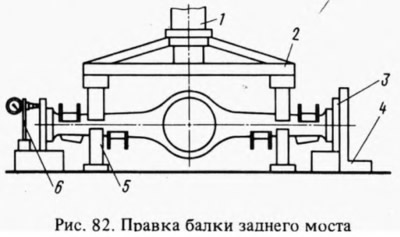
Rack 6 with an indicator is installed so that the indicator leg rests against the upper part of the side surface of the flange, and the indicator pointer is at a division equal to the value of the beam deformation, measured with a probe when straightening the beam.
Installed under the beam (in the deformation zone) restrictive stops 5, rule it with a hydraulic press sequentially in the horizontal and vertical planes, controlling the results of straightening with a probe using a square 4 or an indicator. The maximum force of the press at the place of application of the load should not exceed 10,000 kgf, so that excessive deformation of the casing section does not occur.
With the stop height 5 correctly selected empirically, the beam can be corrected without using a square or indicator, followed by checking it for the absence of deformations.
Remove the beam from the press and check it as above, replacing the flanges 3 (A.70172) for testing.
In the absence of proper equipment, as an exception, it is allowed to straighten the beam sequentially on each side, but with a mandatory check of the deformation of the beam on both sides.