
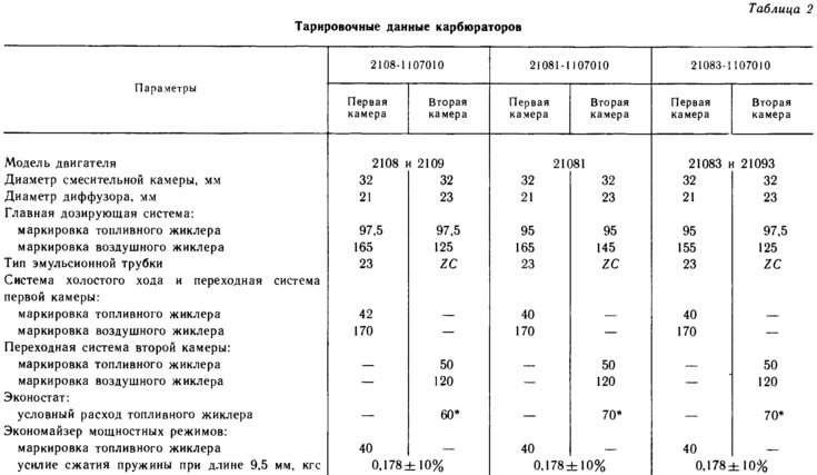
- 1.3 l (cars VAZ-2108 and 2109) — 2108-1107010;
- 1.1 l (car VAZ-21081) — 21081-1107010;
- 1.5 l (cars VAZ-21083,21093) — 21083-1107010.
All these carburetors differ from each other only in certain parameters of calibration data (see table. 2).
Carburetor (pic. 45) - emulsion type, with a falling flow, two-chamber with sequential opening of throttle valves. The carburetor has a balanced float chamber, heating of the throttle zone of the first chamber at the emulsion outlet from the idle system, blocking of the second chamber when the air damper is not fully open.
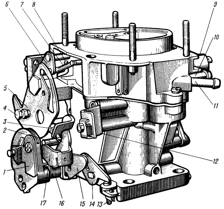
Pic. 45. Carburetor 2108-1107010:
1 - throttle control sector with a bracket; 2 - pin of the lock lever of the second chamber; 3 - adjusting screw for slightly opening the throttle valve of the first chamber; 4 - screw for fastening the air damper drive rod; 5 - air damper control lever; 6 - air damper lever; 7 - air damper return spring; 8 - diaphragm rod of the starting device; 9 - electromagnetic shut-off valve; 10 - fuel supply pipe; 11 - branch pipe for draining part of the fuel into the fuel tank; 12 - bracket for fastening the shell of the draft of the air damper drive; 13 - adjusting screw of the second chamber; 14 - throttle lever of the second chamber; 15 - throttle actuator lever of the second chamber; 16 - throttle return spring of the first chamber; 17 - throttle control lever.
The carburetor has two main dosing systems, a transition system and an idle system with an electromagnetic shut-off valve of the first chamber, a transition system of the second chamber, an econostat, an economizer of power modes, a diaphragm accelerator pump, a diaphragm starter. In addition, the solenoid shut-off valve and the limit switch for the idle mixture adjusting screw, complete with the electronic control unit and the electrical wires connecting them, make up the positive idle economizer.
The carburetor is mounted on the intake manifold on four studs and fastened with nuts. A heat-insulating spacer and a heat shield are placed under the carburetor.
The balancing of the float chamber is carried out using two holes with a diameter of 4 mm, connecting the float chamber to the air filter.
A crankcase exhaust system is attached to the carburetor, for which a branch pipe and a calibrated hole are provided that go into the throttle space of the first chamber. A hole with a diameter of 1.5 mm does not have a noticeable effect on the depletion of the combustible mixture with closed throttle valves at idle.
To heat the throttle zone of the first chamber, a heating unit is screwed to the carburetor body, through which the cooling system fluid passes. The heating unit, due to surface contact with the carburetor body, prevents icing of the emulsion outlet area and the throttle valve. In cases of icing, there may be jerks of the car at small accelerations or the engine stalling when switching to idling.
The blocking of the second chamber does not allow, if the air damper is not fully open, opening the throttle of the second chamber in any engine operating mode. This excludes the operation of the second mixing chamber when the engine is cold. Lock lever with pin 2 (see fig. 45) mounted pivotally on the throttle control lever 17 (The lock lever is not visible in the picture). When the air damper is not completely closed, the air damper control lever 5 acts with the outer edge on the pin 2 and disengages the lock lever from engagement with the second chamber throttle actuator lever 15. In this position, when opening the throttle valve of the first chamber, the lever 15 will not rotate and act on the lever 14 of the throttle valve of the second chamber, which is rigidly mounted on the damper axis.
When the air damper is fully open, lever 5 releases pin 2 and the lock lever will be pressed against lever 15 under the action of the spring. therefore, both lever 14 and the throttle valve of the second chamber (sequential throttle opening). Full opening of the throttle valves will occur simultaneously.
The carburetor consists of two body parts: a body and a cover. The cover has inlet mouths of the first and second chambers, wells for the passage of air to the main air jets and two channels for balancing the float chamber, connecting it with the cavity behind the air filter element. An air damper is installed in the neck of the first chamber. Lever 6 (see fig. 45) damper has two pins, one of which is connected to the spring that closes the damper. The second pin enters the groove of the lever 5 of the air damper control. The groove has a certain profile. Lever 5 is pivotally mounted on the carburetor cover and connected by a rod to the handle in the car.
The body of the diaphragm starter with an adjusting screw, diaphragm and stem 8 is attached to the carburetor cover. An electromagnetic shut-off valve 9 is installed on the carburetor cover. The cover has channels and jets of idle, transition systems and an econostat.
A needle valve for fuel supply, a float, a fuel filter, a fuel supply pipe 10 and a fuel drain pipe 11 into the tank are installed in the cover. Branch pipe 11 has a calibrated hole with a diameter of 0.70 mm. A constant level float chamber encloses the mixing chambers on both sides so that the carburetor can withstand significant tilts without interrupting normal operation. The fuel level fluctuates around a fixed point, in the zone of which the emulsion wells of the main dosing systems are placed. Fuel is taken from the float chamber below this point. In connection with this shape of the chamber and the need to withstand significant inclinations of the carburetor, the float is made double with one bracket having a tongue that provides contact with the needle valve damper ball.
A sealing gasket is installed between the cover and the carburetor body.
Large diffusers are cast together with the carburetor body, small diffusers are inserted into it, cast together with the sprayers of the main dosing systems. The housing contains channels for these systems, idle systems, transitional systems, power modes economizer and accelerator pump. Accelerator pump atomizers with a ball fuel supply valve, main fuel jets and main air jets with emulsion tubes are installed in the housing.
To the tide of the carburetor body, which forms the working cavity of the accelerator pump, a cover with a drive lever and a working diaphragm of the accelerator pump are attached with four screws. The pump is driven by a cam on the axis of the throttle valve of the first chamber. The cover of the power mode economizer with a diaphragm and a ball valve is also attached to the body.
Throttle valves of the first and second mixing chambers of the carburetor are installed in the body. The dampers are fastened with screws on the axles, the screws are caulked out from self-unscrewing. On the axis of the throttle valve of the first chamber, levers 17 and 15 for controlling the throttle valves with the control sector U are installed. Lever 14 is placed on the axis of the throttle valve of the second chamber, which is actuated from the drive lever 15.
The throttle control lever 17 has an adjusting screw 3 for slightly opening the throttle valve of the first chamber. When the lever 5 is turned, the air damper is closed, while the throttle valve of the first chamber is slightly opened by the adjusting screw 3. The carburetor body also has adjusting screws for the quantity and quality of the idle mixture. The holes of the mixture quality adjusting screw are closed with a plastic plug.