




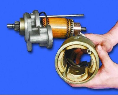
Four excitation windings are fixed in the starter housing.
Attention! Disassemble the traction relay only if it needs to be repaired.
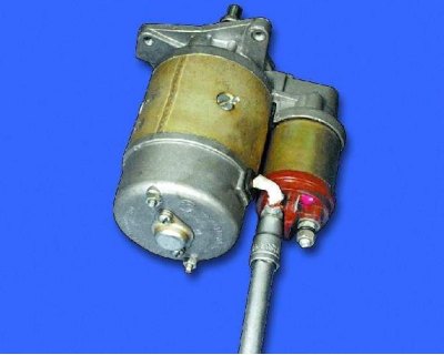
1. Remove the nut from the lower contact bolt.
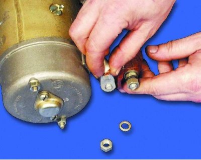
2. Remove the washer and disconnect the stator winding terminal tip.
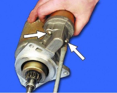
3. Loosen the two screws securing the traction relay.
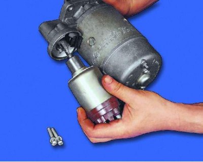
4. Remove the traction relay. To do this, disconnect the relay anchor from the lever by lifting the relay.
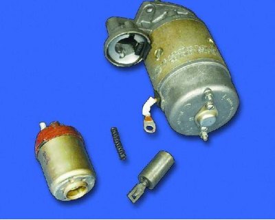
5. Remove the anchor and spring from the traction relay.
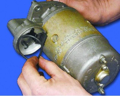
6. Remove the sealing ring.
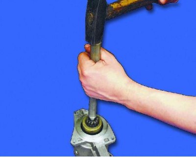
7. Using a tube of suitable diameter, knock the restrictor ring off the retaining ring (see note).
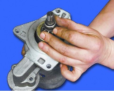
Note: The stop ring is secured by a locking ring installed underneath it.
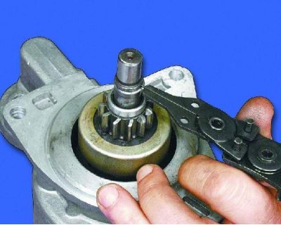
8. Remove the retaining ring.
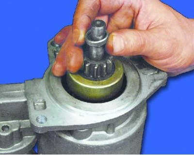
9. Remove the restrictor ring.
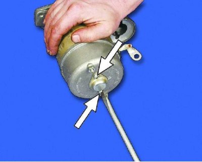
10. Loosen the two mounting screws and remove the protective cover.
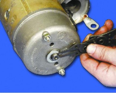
11. Remove the retaining ring...
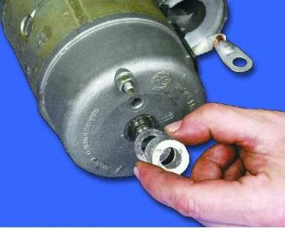
12....and then the adjusting washers.
(The original is on the portal VAZBOOK)
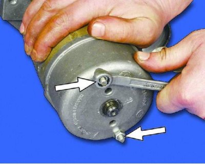
13. Loosen the tie rod nuts.
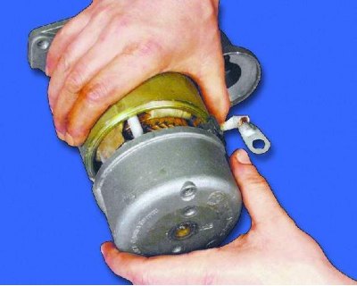
14. Remove the cover from the manifold side.
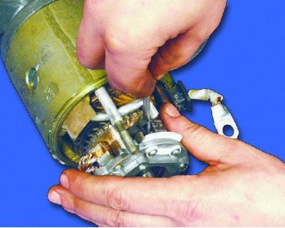
15. Press the springs of both insulated brushes with a screwdriver and remove the brushes from the brush holder.
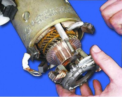
16. Remove the brush holder (see note).
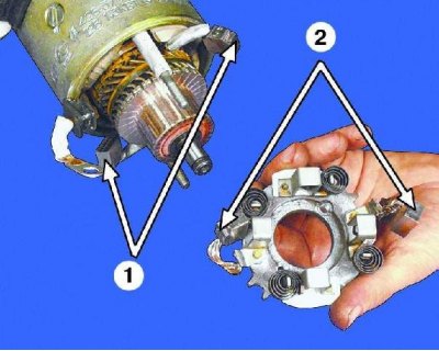
1 – insulated brushes
2 – non-insulated brushes
Note: Insulated brushes are soldered to the stator winding terminals, and non-insulated brushes are soldered to the brush holder. When the brush holder is removed, the insulated brushes remain on the stator winding terminals.
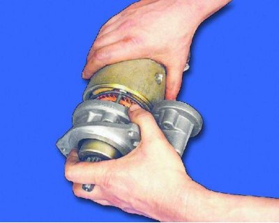
17. Remove the housing with the stator.
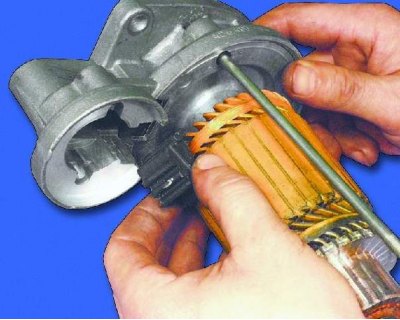
18. Remove the plastic lever stop.
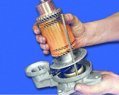
19. Remove the anchor from the drive side cover.
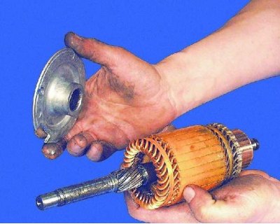
20. Remove the intermediate support from the armature shaft.

21. Remove the retaining ring from the starter drive.
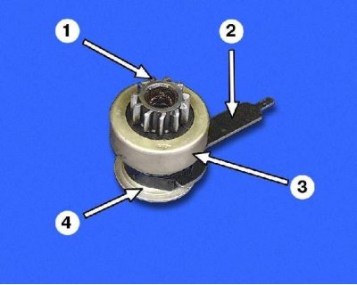
Starter drive parts: 1 – gear; 2 – drive lever; 3 – overrunning clutch; 4 – disc washer
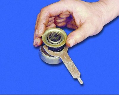
22. Remove the disc washer.
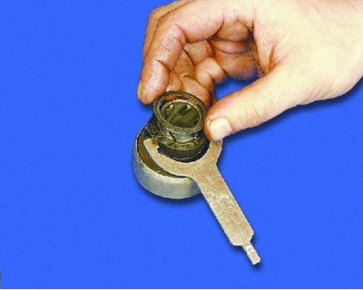
23. Remove the thrust washer.
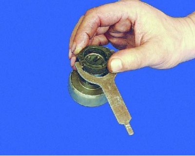
24. Remove the clutch with the lever.
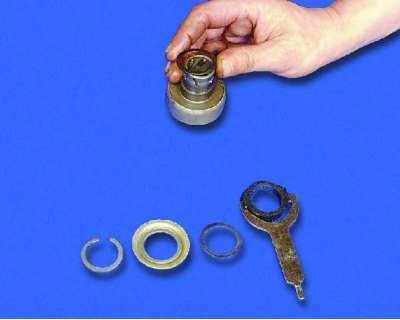
25. Remove the thrust ring.
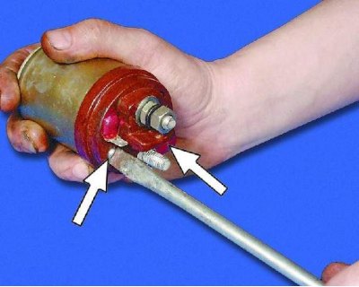
26. Unscrew the two screws securing the traction relay cover.
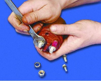
27. Remove the nuts from the two contact bolts of the traction relay (see note).
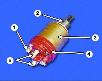
Traction relay details: 1 – winding terminals; 2 - anchor; 3 – body; 4 – lid; 5 – contact bolts
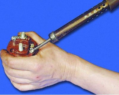
28. Using a soldering iron, disconnect both winding leads from the traction relay terminals.
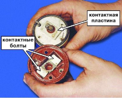
29. Remove the traction relay cover.
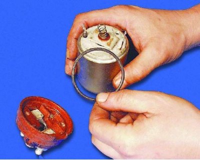
30. Remove the sealing ring.

31. Remove the contact plate assembly with the rod.
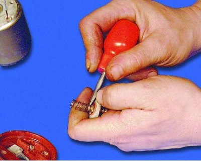
32. Remove the return spring from the rod.
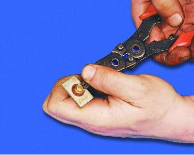
33. Remove the retaining ring.
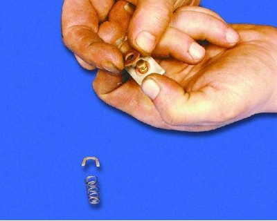
34. Remove the insulating washer.
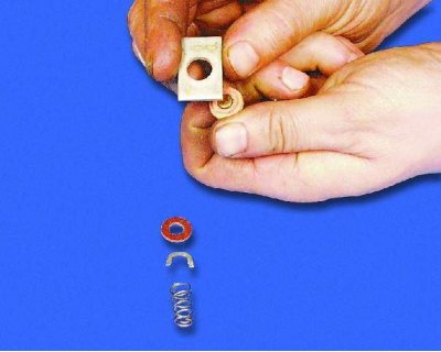
35. Remove the contact plate (see note on the right).
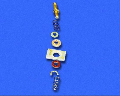
Note: Contact plate mounting details (shown in order of installation on the rod).
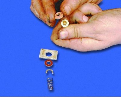
36. Remove the insulating sleeve.
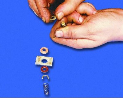
37. Remove the washer.
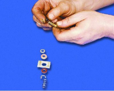
38. Remove the damper spring.
The traction relay windings are installed in a non-separable housing.
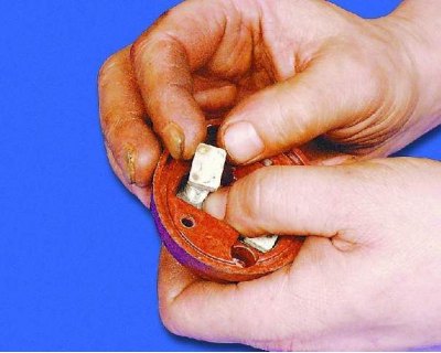
39. Remove the contact bolts from the cover.