
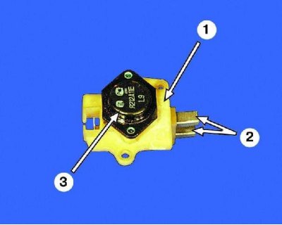
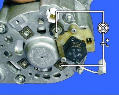
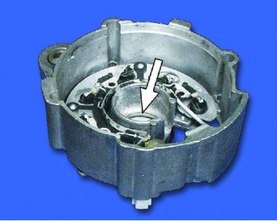
1 - brush holder; 2 - brushes; 3 - voltage regulator
Attention! When checking with a voltage of 220 V, be careful - do not touch the live parts of the generator with your hands.
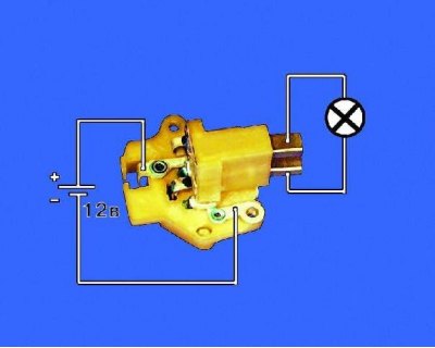
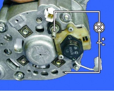
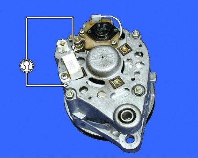
1. Check the voltage regulator. Connect a 12 V test lamp to the brushes. Apply 12V voltage: "+" on the clamp, and "–" on "mass" brush holder. The control lamp should light up.

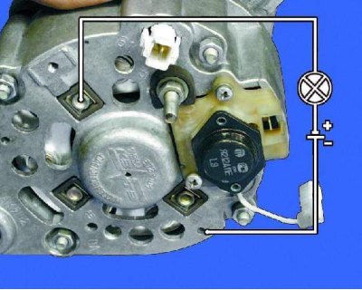
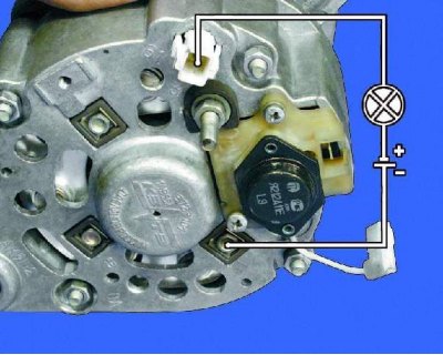
2. Increase the voltage to 15-16 V - the lamp should go out. If the lamp does not go out or does not light up at 12 V, replace the regulator with brush holder.
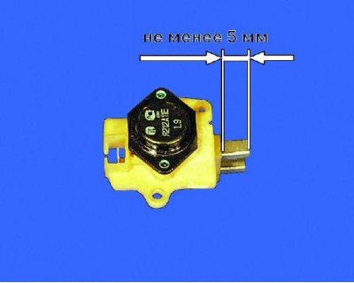
3. Check the ease of movement of the brushes in the brush holder and their protrusion. If the brushes protrude from the brush holder by less than 5 mm, replace the voltage regulator with the brush holder. If chips or cracks are found on the brushes, replace the regulator.
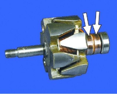
4. Inspect slip rings. If they have scuffs, marks, scratches, wear marks from brushes, etc., the rings must be ground. If damage to the rings cannot be removed with sandpaper, turn the rings on a lathe, removing the minimum layer of metal, and then sand.
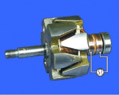
5. Check with an ohmmeter (tester) resistance of the rotor winding by connecting it to slip rings. If the ohmmeter shows "∞", then there is a break in the windings and the rotor needs to be replaced.
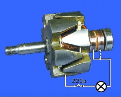
6. Check with a test lamp if there is a winding short circuit to the rotor housing. Turn on the test lamp in a 220 V AC mains (can use rechargeable battery and 12V lamp). Connect one of the wires to the rotor housing, and the second in turn to each ring. In both cases, the lamp should not light. If the lamp lights up, then the winding is closed: the rotor must be replaced.
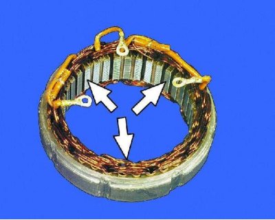
7. Examine the stator. On the inner surface of the stator there should be no traces of armature touching the stator. If there is wear, the bearings or generator covers must be replaced.
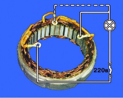
8. Check for an open in the stator winding. To do this, turn on the test lamp in a 220 V AC mains (can use rechargeable battery and 12V lamp). Alternately connect a test lamp between all terminals of the winding. In all three cases, the lamp should be on. If the lamp does not light up, there is a break in the winding. Replace stator or winding.
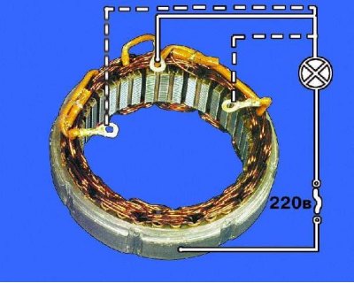
9. Check if there is a short circuit in the stator windings to the housing. To do this, turn on the test lamp in a 220 V AC mains (can use rechargeable battery and 12V lamp). Connect the lamp to the stator winding terminal, and the wire from the current source to the stator housing. If the lamp lights up, then there is a short circuit: it is necessary to replace the stator or winding.
10. Check the rectifier diodes with a 12V test light and battery. To test for shorts in the positive and negative diodes, connect " " to the battery through the control lamp to the terminal "30" generator, and "–" batteries - to the generator housing. If the lamp lights up, then there is a short circuit in the diodes and the unit must be replaced.
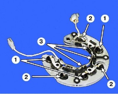
Rectifier block: 1 - positive diodes; 2 - negative diodes; 3 - additional diodes
Note. You can check the rectifier unit without removing the generator from the car. To do this, disconnect the wires from the battery and the generator, and also remove the block with the wire from the voltage regulator terminal. Check the rectifier unit as described in point 10.
11. To test positive diodes, connect " " battery through the control lamp to the terminal "30" generator, and the wire coming from "–" battery - to one of the bolts securing the rectifier unit. If the lamp is on, then there is a short circuit in the positive diodes: the unit must be replaced.
12. To test negative diodes, connect " " battery through a test lamp to one of the rectifier block mounting bolts, and the wire coming from "–" battery - to the generator housing. If the lamp lights up, then there is a short circuit in the negative diodes: the unit must be replaced.
A burning lamp when checking negative diodes may also indicate a short circuit in the stator winding to the generator case, however, such a malfunction is much less common than short circuit diodes.
13. To test additional diodes, connect a wire " " from the storage battery through the control lamp to the terminal "61" generator, and the wire coming from "–" battery - to one of the bolts securing the rectifier unit. If the lamp lights up, then there is a short circuit in the additional diodes. The block needs to be replaced.
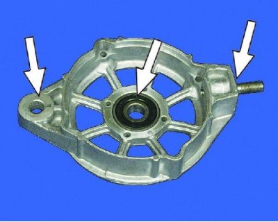
14. Inspect the generator cover from the drive side. If there are cracks, especially at the generator mounting points, replace the cover. Measure the diameter of the bearing seat in the drive end cap. If the bearing hole is deformed or its diameter exceeds 42 mm, replace the cap.
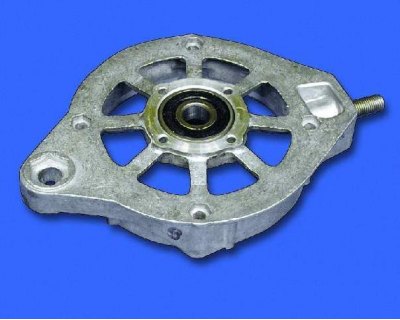
15. Check the ease of rotation of the bearings. If during rotation of the bearings there is play between the rings, rolling or jamming of the rolling elements, the bearings must be replaced. Also replace bearings with damaged protective rings or traces of grease leakage.
16. Inspect the generator cover from the side of the slip rings. If the bearing seat is damaged or worn, replace the cover.
17. The health of the capacitor can be checked with a megger or tester (on a scale of 1–10 MΩ). Connect one tester probe to the capacitor terminal, and the second one to the generator case. Before connecting, the device shows "Ґ". At the moment of connection, the resistance should decrease, and then return to its previous position: in this case, the capacitor is good. A defective capacitor must be replaced.