




- multimeter;
- power supply with adjustable voltage up to 20 V or battery charger.
Removal
1. Prepare the vehicle for work and disconnect the wire terminal from the negative terminal of the battery (see "Preparing the car for maintenance and repair").
2. Disconnect the wire connector from the generator terminal "D".
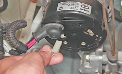
3. Remove the protective rubber cover and use a socket wrench by 10 mm unscrew the nut securing the wire tips to the "+" terminal of the generator.
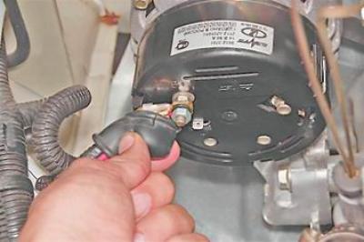
4. Remove the tips of the two wires from the contact bolt.
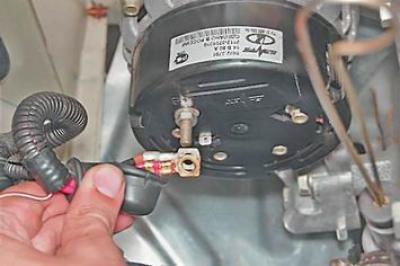
5. Release the three spring clips securing the rectifier block casing and remove the casing from the generator.
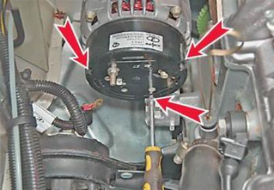
6. Using a Phillips screwdriver, unscrew the two screws securing the voltage regulator.
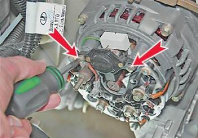
7. Remove the voltage regulator and disconnect the wire connector from its terminal.
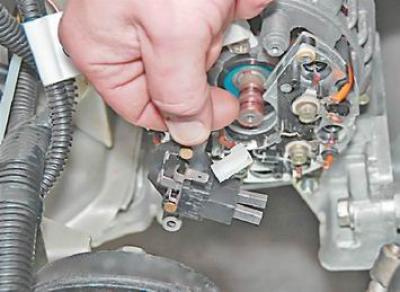
Examination
1. Inspect the voltage regulator brushes to make sure they are mobile. If the brushes are broken or badly worn (they protrude from the brush holder no more than by 5 mm), or they get stuck in the brush holder, the regulator must be replaced.
2. To check the voltage regulator, assemble the circuit (see below). Connect the test lamp to the regulator brushes. Connect the negative terminal of the power source to the regulator "ground" with a wire, and the positive terminal to its terminal.
Warning! When connecting the wires that supply voltage to the voltage regulator, strictly observe the polarity. Incorrect connection of the wires will damage the functioning regulator.
We use a voltmeter to control the voltage supplied to the regulator.
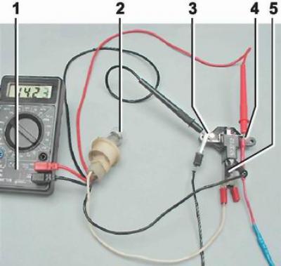
Voltage regulator test circuit: 1 - multimeter (in voltmeter mode); 2 - control lamp; 3 - "ground" of the regulator; 4 - regulator output; 5 - brushes
3. Turn on the power supply and apply 13 V to the regulator. The control lamp should light up, indicating that with such voltage in the vehicle's on-board network, the excitation current will flow to the generator rotor winding.
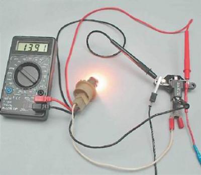
4. Gradually increase the voltage until the control lamp goes out. The voltage at which the control lamp goes out should be 14.5-14.7 V.
5. Reduce the supplied voltage until the control lamp lights up again. The voltage at which the control lamp lights up should not be lower than 13.2 V.
We replace the faulty voltage regulator.
Installation
We install the voltage regulator in the reverse order of removal.