
- multimeter;
- power supply with adjustable voltage up to 20 V or battery charger.
Removing
1. We prepare the car for work and disconnect the wire block from the negative terminal of the battery (see "Preparing the car for maintenance and repair").
2. Disconnect the wire block from the output D of the generator and remove the protective cap.
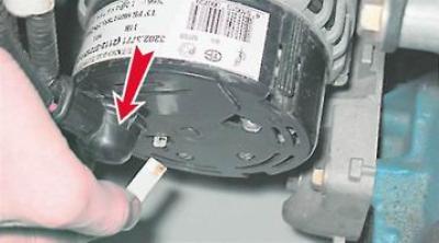
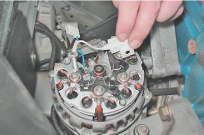
3. Key by 10 mm unscrew the nut that secures the wire lugs to the terminal "+" generator.
4. Remove the tips of the two wires from the contact bolt.
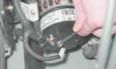
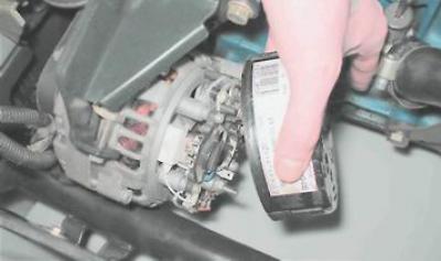
5. We release the three spring clips securing the casing of the rectifier unit...
... and remove the casing from the generator.
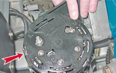
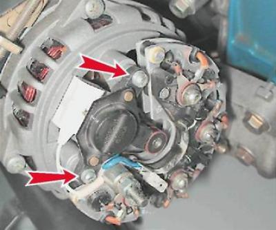
Using a Phillips screwdriver, unscrew the two screws securing the voltage regulator.
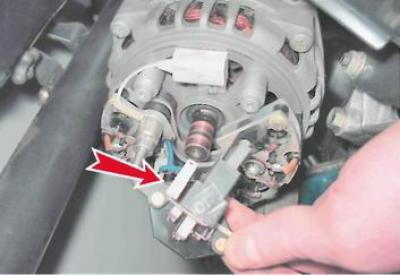
6. Remove the voltage regulator and disconnect the wire block from its output.
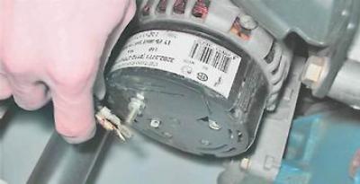
7. Key by 10 mm unscrew the nut securing the tip of the capacitor wire. Using a Phillips screwdriver, unscrew the screw securing the capacitor.
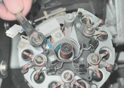
8. Remove the capacitor.
Examination
1. Inspecting the brushes of the voltage regulator, we are convinced of their mobility. If the brushes are broken or badly worn (protrude from the brush holder no more than by 5 mm) or they are wedged in the brush holder, the regulator is replaceable.
2. To check the voltage regulator, we assemble a circuit (see below). We connect the control lamp to the regulator brushes. TO "mass" We connect the negative terminal of the power source with a wire, and the positive terminal to its terminal. We connect the control lamp to the brushes of the voltage regulator.
Warning! When connecting the wires supplying voltage to the voltage regulator, strictly observe the polarity. Incorrect wiring will destroy a working regulator.
With a voltmeter, we control the voltage supplied to the regulator.
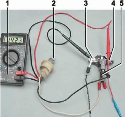
Voltage regulator test circuit: 1 - multimeter (in voltmeter mode); 2 - control lamp; 3- "weight" regulator; 4 - output of the regulator; 5 - brushes
3. Turn on the power supply and apply 13 V to the regulator. The control lamp should light up, indicating that at such a voltage in the vehicle's on-board network, the excitation current will flow to the generator rotor winding.
4. Gradually raise the voltage until the control lamp goes out. The voltage at which the control lamp goes out should be 14.5-14.7 V.
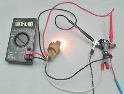
5. Reduce the applied voltage until the control lamp lights up again. The voltage at which the control lamp turned on should not be lower than 13.2 V.
Comment. Capacitor capacitance can only be measured with a special device. You can verify the failure of the capacitor using an ohmmeter with a measurement limit of at least 1000 kOhm
6. We connect an ohmmeter to the terminals of the capacitor and observe its readings. If the capacitor is not "broken", then when the device leads are connected to it, the ohmmeter at the first moment will show a small resistance, then this resistance will increase rapidly until it stabilizes. A similar change in the readings of the ohmmeter should be repeated when the polarity of the device is changed.
We replace the faulty capacitor and voltage regulator.
Installation
Install the capacitor and voltage regulator in reverse order.