




Inspection and operation rules
To avoid damaging the regulator during testing and operation, the following rules must be observed.
You must not mix up the wires connected to the "15" and "67" plugs (see fig. 159). If the wires are inadvertently mixed up, the regulator will not work and the upper contacts will be permanently closed. The voltage at the generator output will increase greatly, which will lead to violent boiling and splashing of electrolyte from the battery, as well as damage to consumers by increased voltage. In addition, the upper contacts will sinter and the voltage regulator will have to be replaced.
It is not allowed to connect capacitors against radio interference to the circuit between the plugs "67" of the regulator and the generator. This violates the operating conditions of the contacts, and they are quickly damaged.
Additional power consumers should not be connected to the generator excitation winding power supply circuit, as this will greatly increase the generator voltage.
It is forbidden to check the functionality of the regulator by short-circuiting its plugs "15" and "67". In this case, the generator voltage increases and the rectifier may be damaged.
It is not recommended to remove the regulator cover unnecessarily, so as not to damage the seal. Moisture and dust getting under the cover leads to contamination, burning of contacts and, consequently, disruption of the normal operation of the regulator. Therefore, all materials used in the regulator are tested for the absence of gas emission. If it is necessary to replace the gasket, the new gasket must be made only of polyurethane, as provided for by the regulator design.
The regulator should be kept clean and protected from accidental impacts that may disrupt its adjustment. It is also necessary to monitor the reliability of the connection of the regulator body to the ground through the mounting screws, since a poor connection increases the generator voltage above the norm.
Testing and adjustment on the stand
The regulator is tested and adjusted on a stand that has a generator, a battery, a thermostat and an electric motor with adjustable rotation speed over a wide range (Fig. 160). The regulator with the lid closed is installed on the stand with the plugs facing down.
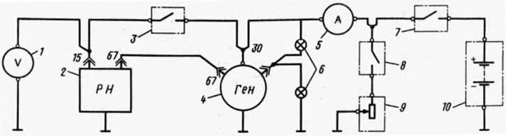
Fig. 160. Circuit diagram for testing the voltage regulator on a bench:
1 - voltmeter with a scale of 15 V, accuracy class not lower than 0.5; 2 - voltage regulator; 3 - main switch; 4 - generator; 5 - ammeter with scale up to 50 A; control lamps 3 W, 12 V; 7 - Battery switch; 8 - rheostat switch; 9 - rheostat 5-30 A,
15 V; 10- battery
Particular attention should be paid to the reliability of the wire connections so that their resistance is minimal. It is necessary that the wires from switch 3 are connected directly to the generator clamp "30" and the regulator plug "15", and the regulator body is connected directly to the generator body. All connecting wires should be as short as possible. If tray wiring is used on the stand, the trays must be made of non-magnetic material.
During control tests on the bench, do not allow the regulator to operate with the battery disconnected, as this may damage the regulator contacts.
Light bulbs 6 monitor the generator's serviceability and, if it is in good condition, should have the same glow.
Before testing, the regulator is heated in a thermostat for 15-18 minutes at (50±3)°C, supplying the regulator winding with current at a voltage of 12-13 V. The voltage is set by rheostat 9 with switches 3 on and the generator not running.
Immediately after warming up, check and adjust. During check and adjusting both the 1st and 2nd stages, make sure that the voltage was stable, i.e. it did not fluctuate sharply.
2nd stage control. The generator rotor is set in rotation and brought to 5000 rpm. The generator load current is set to 2-12 A using a rheostat. The generator voltage is checked, which should be (14.2±0.3) V. If it is different, the generator is stopped, the battery is disconnected, the cover is removed from the regulator and, by bending bracket 12 (see fig. 159), loosen if the voltage is high, or increase if the voltage is low, the tension of spring 11. Then put the regulator cover back in place and check the voltage of the 2nd stage again.
After completing the check and adjustment of the 2nd stage, immediately check the 1st stage.
1st stage control. At a rotor speed of 5000 rpm, the rheostat 9 sets the load current to 25-35 A. In this case, the voltage should be no more than 0.7 V lower than the value obtained when adjusting the 2nd stage.
If the voltage does not fit within these limits, then stop the generator, disconnect the battery, remove the generator cover, loosen nut 6 (withm. fig. 159) and move stand 8 by 0.1–0.2 mm.
When the voltage is high, the post is moved down, and if it is low, it is moved up. At the same time, post 7 is moved to maintain a gap of (0.45±0.1) mm between the contacts of the 2nd stage. During this operation, it is necessary to monitor the contacts of the 1st and 2nd stages. The anchor contact should not go beyond the contacts on the posts.
Tighten nut 6, put the cover back in place, and check the regulator again (both 1st and 2nd stages) and, if necessary, repeat the operations until precise adjustment is achieved.
After adjustment is complete, the regulator cover is cleaned and installed on the hot regulator to minimize moisture absorption.