
Note: Voltage Regulator, Rectifier and Capacitor checks shown above (see relevant sections). You can check the stator and rotor windings for an open circuit without removing the generator from the car. To do this, you need to remove the rectifier unit.
To complete the work you will need:
- three or two-jaw puller;
- homemade mandrel from the cup puller kit.
Disassembly
1. Remove the generator from the car (see above, "Generator - removal and installation").
2. Remove the voltage regulator (see "Voltage regulator - check and replacement).
3. Remove the rectifier unit along with the capacitor (see "Rectifier unit and capacitor - check and replacement").
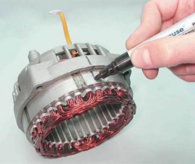
4. Mark with a marker the relative position of the front and rear covers of the generator (to simplify assembly).
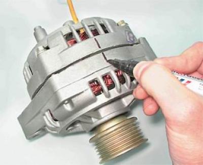
5. socket wrench by 8 mm unscrew the four bolts that tighten the front and rear covers of the generator.
6. With a slotted screwdriver, carefully push the covers of the generator apart.
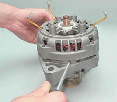
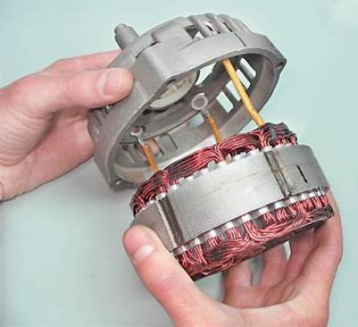
7. Disconnect the back cover along with the stator winding from the front cover.
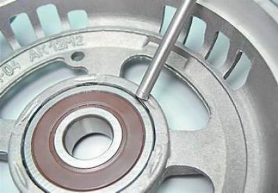
Recommendation: To determine the technical condition of the rear bearing, shake from side to side and vigorously rotate its outer ring. The bearing should not have significant play, the ring should rotate freely without jamming and extraneous noise. A defective bearing must be replaced.
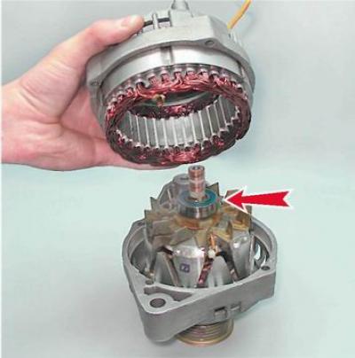
8. Mark with a marker the relative position of the stator and the rear cover.
9. We take out the stator from the rear cover of the generator.
10. To determine the technical condition of the front bearing, holding the pulley with your hand, rotate and shake the front cover from side to side.
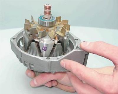
Recommendation: If the bearing seizes, has significant play, or makes a lot of noise when the cover is turned vigorously, it must be replaced.
Tip: The manufacturer does not recommend changing the front rotor bearing as the bearing is rolled into the front cover of the generator. But, given that the cost of the bearing is much lower than the cost of a new front cover and, especially, the generator assembly, it is advisable to press out and replace the faulty bearing.
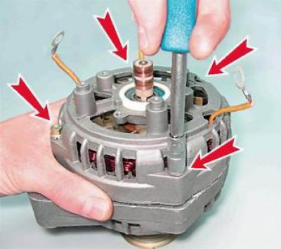
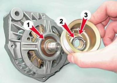
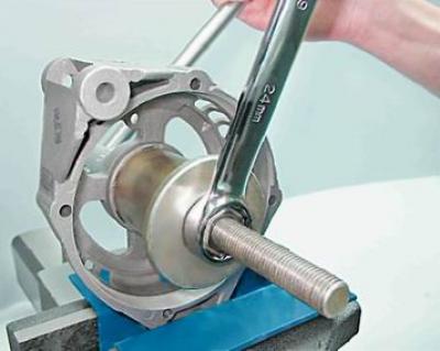
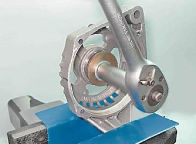
11. If it is necessary to replace the front bearing of the generator with a socket wrench by 24 mm unscrew the pulley fastening nut, holding the pulley with sliding pliers.
12. Remove the pulley from the rotor shaft (3) with spring and flat washers (2), spacer (1).
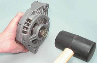
13. We screw the pulley fastening nut onto the threads of the rotor shaft (flush with end). By blows of a hammer with a rubber striker on the nut, we press the rotor out of the front bearing.
14. If it is necessary to replace the front bearing of the generator, install the front cover in a vise.
15. Having selected suitable mandrels from a set of cup puller, we press out the bearing from the mounting hole of the front cover.
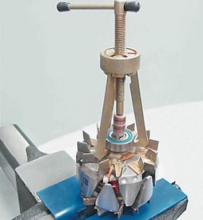
16. Having fixed the rotor in a vice with soft pads on the jaws, using a universal puller of a suitable size, we press the rear bearing from the rotor shaft.
Examination
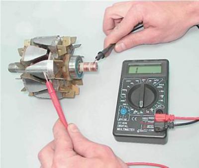
1. Applying the ohmmeter probes to the slip rings of the rotor, we check the excitation winding for an open circuit. The resistance of a good excitation winding should be 5-10 ohms.
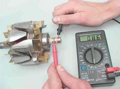
2. By connecting the ohmmeter probes to any slip ring and to the rotor, we check the excitation winding for a short circuit to "mass". With a good rotor winding, the ohmmeter should show an infinitely large resistance.
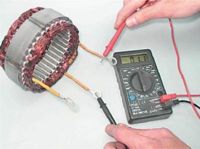
3. Alternately connecting the ohmmeter probes to the terminals of the stator winding, we check the stator windings for an open circuit. In the absence of a break, the ohmmeter will show a small electrical resistance (about 10 ohm).
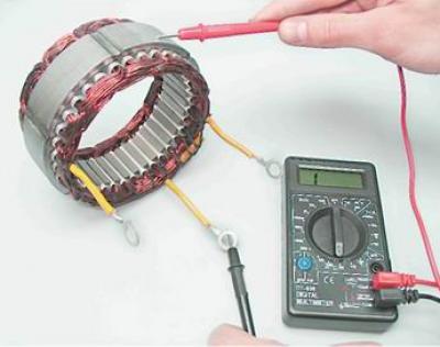
4. By connecting the ohmmeter probes to any winding terminal and to the stator, we check the stator winding for a short circuit to "mass". If there is no short circuit, then the ohmmeter should show infinite resistance.
Replace defective rotor and stator.
Assembly
Warning! Before pressing the bearing into the front cover of the generator, it is necessary to check the seat of the bearing and, if necessary, restore the chamfer with a knife or scraper where the edges of the hole have remained jammed. When pressing the front bearing into the cover, the force must be applied only to the outer ring of the bearing.
1. Having selected suitable mandrels from the cup puller set, we press the new bearing into the front cover of the generator until it stops.
2. Applying light blows with a hammer through a drift, we restore the rolling of the bearing in the cover.
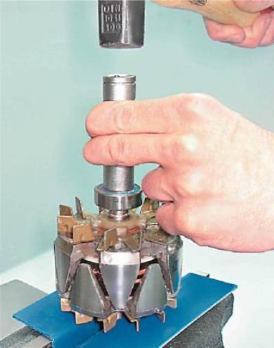
3. Using a tube of suitable diameter (deep head can be used by 19 mm), until it stops, press the rear bearing onto the rotor shaft.
Warning! Before installing the alternator rear bearing, make sure that the shaft is securely clamped in a vise. Place a wooden block of a suitable size under the rotor shaft so that the front impeller of the rotor is not damaged during pressing. To avoid damage to the bearing, strikes should only be applied to the inner ring of the bearing.
Further assembly of the generator is carried out in the reverse order of disassembly. At the same time, we combine the marks applied to the covers and the generator stator. Finally tighten the tie bolts evenly, crosswise, in several steps of half a turn. By tightening the bolts, we are convinced of the easy rotation of the rotor (rotor sticking can be caused by misaligned caps). Before tightening the bolts for fastening the stator winding leads, make sure that insulating washers are placed under their heads.