
English Русский
Български
Беларускі
Український
Српски
Hrvatski
Română
Polski
Slovenský
Magyar
| Articles | Contacts | Sitemap |   
Repair and maintenance Lada Repair and maintenance Mazda Repair and maintenance Mitsubishi Repair and maintenance Toyota Repair and maintenance Land Rover Repair and maintenance Hyundai Repair and maintenance Nissan
VAZbook.ru


Main     1111   2101   2105   2106   2107   2109   2110   2115   2121  
VAZ-2114 (2004-2013) VAZ-2115 (1997-2012)
  • Main
  • «Samara-2»
  • VAZ-2115
  • Chassis
  • Brake system
  • Features of the vacuum booster design

Features of the vacuum booster design (VAZ-2115)

            0

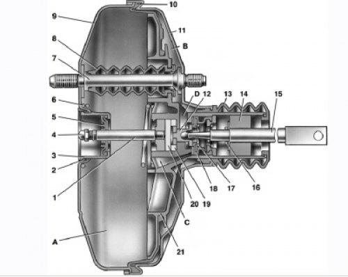
8.2. Vacuum booster: A – vacuum chamber; B – atmospheric chamber; C, D – channels; 1 – rod; 2 –…

8.2. Vacuum booster: A – vacuum chamber; B – atmospheric chamber; C, D – channels; 1 – rod; 2 – sealing ring of the master cylinder flange; 3 – amplifier body cup; 4 – adjusting bolt; 5 – rod seal; 6 – diaphragm return spring; 7 – amplifier pin; 8 – sealing cover; 9 – amplifier body; 10 – diaphragm; 11 – amplifier housing cover; 12 – piston; 13 – valve body protective cover; 14 – air filter; 15 – pusher; 16 – pusher return spring; 17 – valve spring; 18 – valve; 19 – valve body bushing; 20 – rod buffer; 21 – valve body


Rubber diaphragm 10 (Fig. 8.2) together with valve body 21 divide the vacuum booster cavity into two chambers: vacuum A and atmospheric B. Chamber A is connected by a hose to the receiver on the engine intake pipe. Valve body 21 is plastic. At the outlet from the cover it is sealed with a corrugated protective cover 13. Installed in the valve body are rod 1 of the master cylinder drive with a support sleeve, buffer 20 of the rod, piston 12 of the valve body, valve assembly 18, return springs 16 and 17 of the pusher and valve, respectively, air filter 14 and pusher 15.

When the pedal is pressed, the pusher 15, piston 12, and then the valve 18 move until they stop against the valve body seat. At this time, chambers A and B are disconnected. With further movement of the piston, its seat moves away from the valve and through the resulting gap, chamber B is connected to the atmosphere. Air entering through filter 14 into the gap between the piston and the valve and channel D creates pressure on diaphragm 10. Due to the difference in pressure in chambers A and B, the valve body moves together with rod 1, which acts on the piston of the main brake cylinder.


When the pedal is released, the valve moves away from its body and through the resulting gap and channel C, chambers A and B communicate with each other.

When the vacuum booster fails, the force on the brake pedal increases significantly, which negatively affects vehicle control.

Repairing the vacuum booster requires a special tool, so it is recommended to replace it as an assembly.

To check the operation of the vacuum booster with the engine off, press the brake pedal 5-6 times. Keeping the brake pedal depressed, start the engine. The brake pedal should move forward. If this does not happen, first check the tightness of the vacuum hose connections and operation of the check valve.


This article is available at russian, bulgarian, belarusian, ukrainian, serbian, croatian, romanian, polish, slovak, hungarian
The text was reviewed by the specialist: Grigory Vologodtsev

Share with friends:

Previous articles
VAZ-2115: Brake system
Next articles

Possible malfunctions of the brake system
Design features of the brake system
Checking the operation of the vacuum booster check valve
Replacing the vacuum booster
Removal and installation the master brake cylinder
Repair of the main brake cylinder
Replacing the pressure regulator

More articles from other manuals on VAZ cars:
➠ Features of the vacuum booster device VAZ-1111 (1988-1996)
➠ Design features of the cylinder block VAZ-2101 (1970-1983)
➠ Measuring the protrusion of the vacuum booster rod VAZ-2105 (1979-2010)
➠ Vacuum brake booster — checking the functionality VAZ-2106 (1976-2006)
➠ Design features of VAZ-21072 and VAZ-21074 cars VAZ-2107 (1982-2012)
Link in different formats to this page


Visitor comments

No comments yet


How much will 18 + 21 ?


VAZ-2114 (2004-2013) 
  • General information
  • Operation and maintenance
  • Power unit
  • Engine repair
  • Cooling system
  • Supply system
  • Control system
  • Exhaust system
  • Transmission
  • Clutch
  • Car gearbox
  • Front wheel drives
  • Chassis
  • Wheels and tires
  • Front suspension
  • Rear suspension
  • Steering
  • Brake system
  • Body
  • Exterior
  • Interior
  • Doors and glass
  • Tailgate
  • Ventilation and heating
  • Electrical equipment
  • Equipment and devices
  • Headlights and lighting
  • Engine electrics
  • Electrical circuits


VAZ-2115 (1997-2012) 
  • General information
  • Vehicle device
  • Operation manual
  • Vehicle malfunctions
  • Car care
  • Power unit
  • Engine repair
  • Cooling system
  • Supply system
  • Control system
  • Exhaust system
  • Transmission
  • Clutch
  • Car gearbox
  • Front wheel drives
  • Chassis
  • Front suspension
  • Rear suspension
  • Steering
  • Brake system
  • Body
  • Exterior
  • Interior
  • Doors, covers and windows
  • Electrical equipment
  • Equipment and devices
  • Headlights and lighting
  • Engine electrics
  • Anti-theft system


VAZbook.ru © 2017 · Mobile version · Contact with administration · Sitemap: EN BG BY UA RS HR RO PL SK HU · Site search · News and articles VAZ-1111 · VAZ-11113 · VAZ-2101 · VAZ-21011 · VAZ-2104 · VAZ-2105 · VAZ-21051 · VAZ-2106 · VAZ-21061 · VAZ-2107 · VAZ-21099 · VAZ-2109 · VAZ-2108 · VAZ-2110 · VAZ-2112 · VAZ-2114 · VAZ-2115 · VAZ-2121 · VAZ-21213 · VAZ-21214 ·
The site stores technical data using cookies to improve the service.