
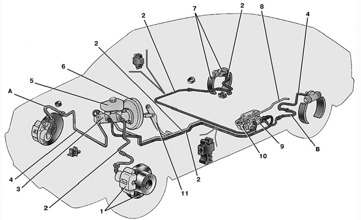
8.1. Scheme of the hydraulic drive of the brakes: And – a flexible hose of a forward brake; B - flexible rear brake hose; 1 – the brake mechanism of a forward wheel; 2 - pipeline circuit left front-right rear brake; 3 - the main cylinder of the hydraulic drive of the brakes; 4 - pipeline circuit right front-left rear brake; 5 – a tank of the main cylinder; 6 - vacuum amplifier; 7 - brake mechanism of the rear wheel; 8 - elastic lever of the pressure regulator drive; 9 - pressure regulator; 10 – pressure regulator drive lever; 11 - brake pedal
The car has a working brake system with a diagonal separation of circuits (pic. 8.1), which greatly improves driving safety. One hydraulic drive circuit ensures the operation of the right front and left rear brake mechanisms, the other - the left front and right rear. If one of the circuits of the working brake system fails, the second circuit is used, which ensures that the car stops with sufficient efficiency.
The hydraulic drive included vacuum booster 6 and dual-circuit pressure regulator 9 in the rear brakes.
The parking brake system is driven by the rear wheel brakes.
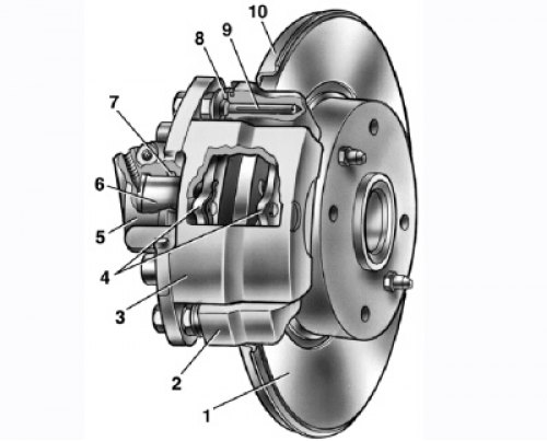
8.6. Front wheel brake: 1 - brake disc; 2 - guide pads; 3 - support; 4 - brake pads; 5 - working cylinder; 6 - piston; 7 - sealing ring; 8 - protective cover of the guide pin; 9 - guide pin; 10 - protective cover
Front wheel brake disk, with automatic adjustment of the gap between the pads and the disk, with a floating bracket.
The bracket is formed by a caliper 3 (pic. 8.6) and working cylinder 5, tightened with bolts. The movable bracket is bolted to the pins 9 installed in the holes of the guide blocks. These holes are lubricated, rubber covers 8 are installed between the fingers and the guide shoe. Brake shoes 4 are pressed against the grooves of the guide by springs.
A piston 6 with a sealing ring 7 is installed in the cavity of the cylinder 5. Due to the elasticity of this ring, an optimal gap between the brake pads and the disc is maintained. In a variant version, pads with pad lining wear indicator can be installed on cars.
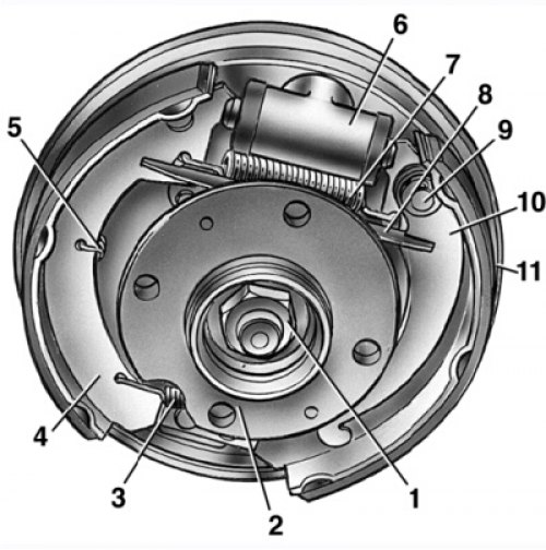
8.7. Rear wheel brake: 1 – a nut of fastening of a nave; 2 - wheel hub; 3 - the lower coupling spring of the shoes; 4 - brake shoe; 5 - guide spring; 6 - working cylinder; 7 - upper coupling spring; 8 - expanding bar; 9 – a finger of the lever of a drive of a parking brake; 10 – parking brake drive lever; 11 – a shield of the brake mechanism
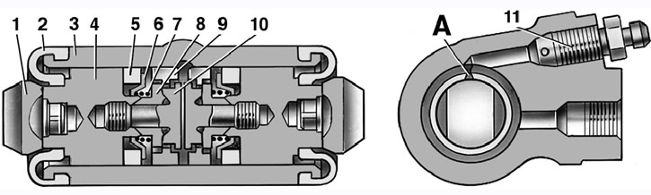
8.8. Rear wheel brake slave cylinder: A - a slot on the thrust ring; 1 - stop pads; 2 - protective cap; 3 - cylinder body; 4 - piston; 5 - sealant; 6 - support plate; 7 - spring; 8 - crackers; 9 - thrust ring; 10 - stop screw; 11 - fitting
Rear wheel brake (pic. 8.7) drum, with automatic adjustment of the gap between the shoes and the drum. The automatic clearance adjustment device is located in the working cylinder. Its main element is a split thrust ring 9 (pic. 8.8), mounted on the piston 4 between the shoulder of the stop screw 10 and two crackers 8 with a gap of 1.25–1.65 mm.
Thrust rings 9 are inserted into the cylinder with an interference fit, providing a shear force of the ring along the cylinder mirror of at least 343 N (35 kgf), which exceeds the force on the piston from the coupling springs 3 and 7 (see fig. 8.7) brake pads.
When, due to the wear of the linings, the gap of 1.25–1.65 mm is completely selected, the shoulder on the stop screw 10 (see fig. 8.8) is pressed against the shoulder of the ring 9, as a result of which the thrust ring is shifted after the piston by the amount of wear. With the cessation of braking, the pistons are shifted by the force of the coupling springs until the crackers stop against the collar of the thrust ring. This automatically maintains the optimal clearance between the shoes and the drum.
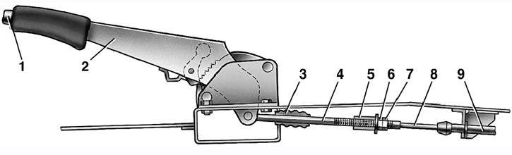
8.9. Parking brake drive: 1 - button for fixing the lever; 2 – the lever of a drive of a parking brake; 3 - protective cover; 4 - thrust; 5 - cable equalizer; 6 - adjusting nut; 7 - locknut; 8 - cable; 9 - cable sheath
Parking brake system with a mechanical drive, acts on the brake mechanisms of the rear wheels. The parking brake drive consists of a lever 2 (pic. 8.9), adjusting rod 4, equalizer 5, cable 8, lever 10 (see fig. 8.7) manual drive of pads and expansion bar 8.
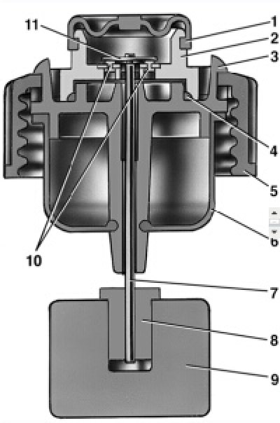
8.10. Brake fluid emergency level sensor: 1 - protective cap; 2 – sensor housing; 3 – sensor base; 4 - sealing ring; 5 - clamping ring; 6 - reflector; 7 - pusher; 8 - bushing; 9 - float; 10 - fixed contacts; 11 - moving contact
Emergency brake fluid level sensor mechanical type.
Pavilion 2 (pic. 8.10) sensor with a seal 4 is pressed against the base 3 by a clamping ring 5 screwed onto the neck of the tank. At the same time, the reflector flange 6 is pressed against the end of the neck. In this position, the clamping ring is held by two clamps made on the base 3.
A pusher 7 passes through the hole in the base, connected to the float 9 with the help of a sleeve 8. On the pusher there is a movable contact 11, on the sensor body there are fixed contacts 10. The contact cavity is sealed with a protective cap 1.
When the level of brake fluid in the reservoir drops to the maximum allowable, the moving contact falls on the fixed contacts and closes the circuit of the emergency brake system warning light in the instrument cluster.
Helpful Hints: Bleed the brakes Without help, there are two ways.
- The first is the most reliable: order an aluminum or bronze cover for the main brake cylinder to the turner, wrap the valve from the chamber into it and connect it with an additional hose to the spare wheel; air pressure should not exceed 0.05–0.07 MPa (0.5–0.7 kgf/cm2).
- The second one is not very reliable, but acceptable: connect the rubber bulb to the fitting of the wheel cylinder - the connection must be very tight. Squeeze the pear, unscrew the fitting; when the pear is half full, tighten the fitting. Repeat the procedure 3-4 times. During test braking, check the operation of the brakes.
The free travel of the brake pedal with the engine off should be 3–5 mm. Too little free play indicates that the wheel cylinder is seized and causes increased fuel consumption and accelerated wear of the brake pads, too much free play is a sign of excessive clearances in the pedal mechanism or a violation of the tightness of the brake system.
If the free play decreases when the pedal is pressed repeatedly, i.e. she becomes «tougher», - air in the system. If the full pedal travel starts to increase, the system is leaking.
If the brake pedal starts to vibrate when braking, most often the cause is warping of the brake discs. Unfortunately, in such a situation, they only need to be changed, and both at once.
If the car starts to pull to the side when braking, check the wheel cylinders: they may need to be repaired or replaced.
If there is a knock in the front suspension that disappears when braking, check the tightness of the two caliper mounting bolts.
After brake pad replacement before driving, be sure to press the brake pedal several times - the pistons in the wheel cylinders should fall into place.