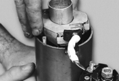
1. Remove the starter from the vehicle (see "Removal and installation the starter").
2. Unscrew the lower contact bolt fastening nut…
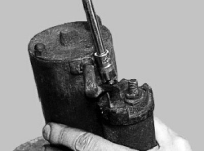
3. …remove the washer and disconnect the stator winding terminal tip.
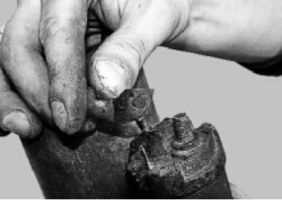
4. Unscrew the two bolts securing the traction relay to the housing…
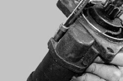
5. …remove the relay…
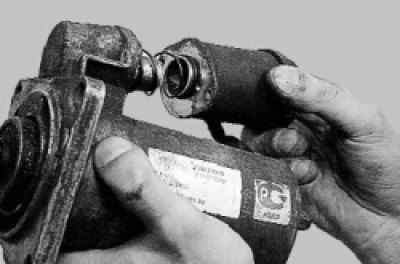
6. …and remove the traction relay anchor from the drive lever.
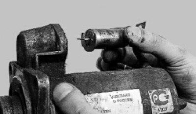
7. Remove the traction relay sealing gasket.
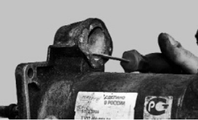
8. Overcoming the resistance of the retaining ring, slide the drive gear limiting ring along the shaft
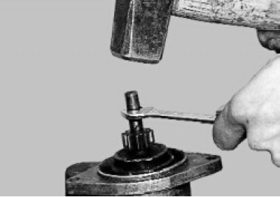
9. Remove the locking… from the drive shaft
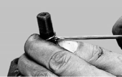
10. …and the limiting rings.
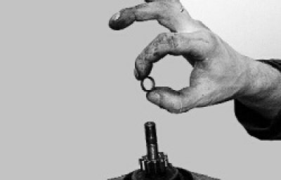
11. Unscrew the two nuts of the tie rods…
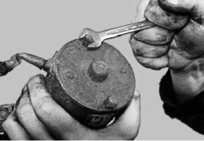
12. …and remove the back cover with the brush holder.
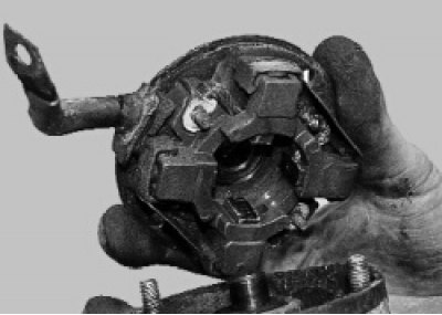
13. Pry up the brush retaining bracket…
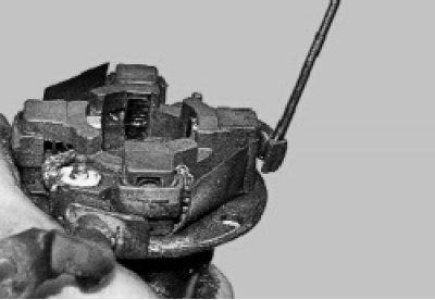
14. …remove the bracket…
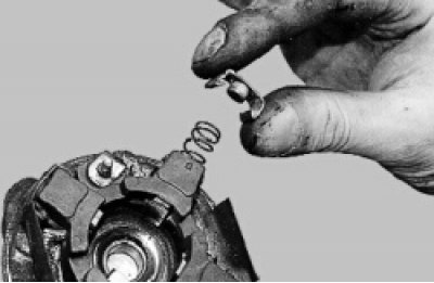
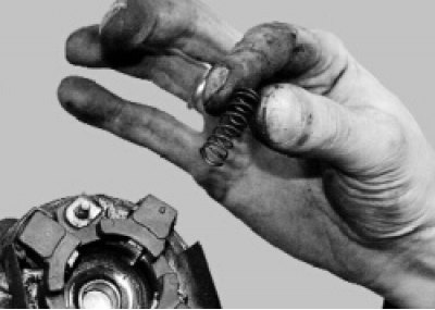
15. …brush spring…
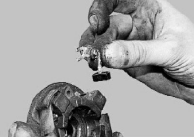
16. …and a brush.
17. Remove the two screws securing the brush holder to the cover…
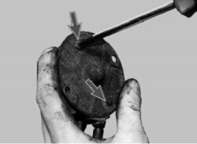
18. …and remove the brush holder.
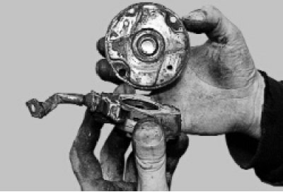
19. Pry up the retainers of the remaining brushes…
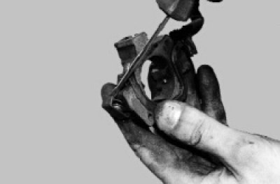
20. … remove the clamps and pressure springs. Replace deformed or damaged clamps and heavily compressed or bent springs.
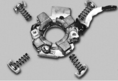
21. Remove the brushes from the brush holder guides.
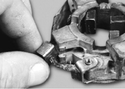
22. Remove the non-insulated brushes.
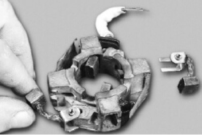
23. Remove the cardboard insulation pad. Replace any torn or excessively compressed pad.
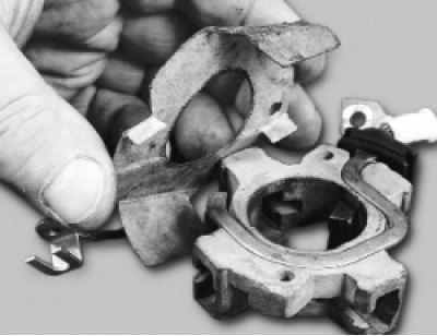
24. Remove the connecting busbar with insulated brushes.
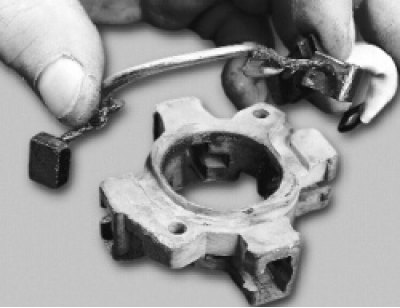
Notes: Replace brushes that are worn to less than 3.5mm between the working surface and the outlet.
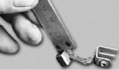
Use a caliper to measure.
25. Remove the starter housing from the cover studs.
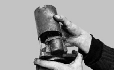
26. Remove the central gear from the armature shaft…
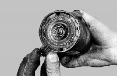
27. …and an intermediate support.
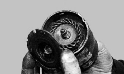
Note: There is a washer installed on the armature shaft on the drive side.
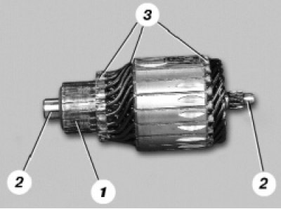
28. Inspect the anchor. If commutator 1 is dirty or has scratches, traces of burning, etc., sand the commutator with fine glass paper. If the commutator is significantly rough or mica protrudes between its plates (lamellas), turn the commutator on a lathe and then sand it with fine glass paper. The runout of the core relative to the shaft journals should not exceed 0.08 mm. Otherwise, replace the anchor. If a yellow bearing deposit is found on shaft 2 of the anchor, remove the deposit with fine sandpaper, as this may lead to jamming of the gear on the shaft. If there are nicks or gouges on the surfaces of the journals and splines of the shaft, replace the anchor. Check the reliability of the soldering of the terminals of winding 3 of the anchor to the commutator plates. Inspect the winding along the ends of the anchor; the diameter of the winding should be less than the iron package of the anchor. Otherwise, replace the anchor.
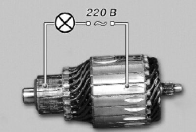
29. Check the condition of the armature winding using a test lamp powered by 220 V alternating current. Apply voltage to the collector plate and the armature core. The lamp should not light. If the lamp lights, then there is a short circuit in the armature winding or the collector plate to ground. In this case, replace the armature.
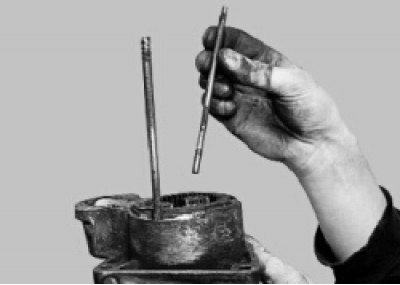
30. Remove the studs from the starter cover on the drive side.
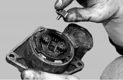
31. Remove the three planetary gears from the drive shaft. If their teeth or the needle bearings mounted in the gears are damaged, replace them.
32. Remove the drive shaft with the lever from the cover.
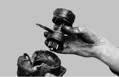
33. Remove the seal.

34. Remove the overrunning clutch assembly with the drive gear from the drive shaft.
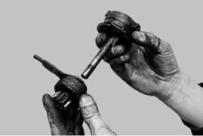
The original is posted on Internet resource: VazBook.ru
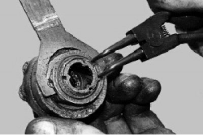
35. Remove the retaining ring…
36. …distance ring…
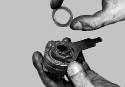
37. …and a lever.
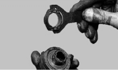
38. Remove the snap ring, shaft support and sun wheel
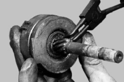
Assemble the starter in the reverse order of disassembly, taking into account the following.
1. Before assembly, lubricate the drive gear teeth with engine oil and consistent grease (CIATIM-201, 202, 203 or Litol-24) drive shaft helical splines, internal gear teeth, planetary gears and rotor shaft splines.
2. The brush holder must be installed in the starter separately from the cover on the collector side, since the brushes are pushed out of the guides by springs and it is impossible to hold them in their original position without a special device. For preliminary assembly and installation of the brush holder, use a thin-walled mounting sleeve 1, the diameter of which is equal to the diameter of the collector or slightly larger (about 30 mm)…
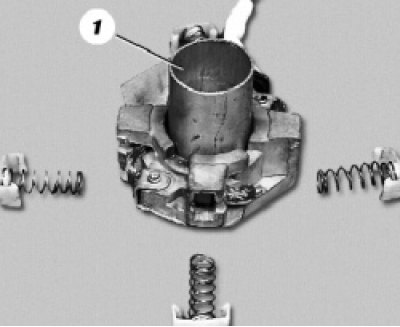
3. …and install the assembled brush holder into the starter housing until it stops, remove the mounting sleeve and install the cover from the collector side.