




All three starters are a DC motor with mixed excitation and an electromagnetic two-winding traction relay. The installation dimensions of the starters are the same. The starters differ in the design of the collector unit and drive.
The starter 29.3708 has a face-type collector, the starter 423.3708 has a cylindrical one, otherwise they are almost identical. The starter 5712.3708 is equipped with a planetary gear in the drive.
The main difference between these starters and traditional starters used in other cars is the absence of a support for the end of the anchor shaft in the cover on the drive side. The support is a bushing pressed into the clutch housing.
Technical characteristics of starter 29.3708 (423.3708)
- Nominal power, kW…..1.3
- Current consumption at maximum power, A, no more than…..260
- Current consumption in the braked state, A, no more than…..500
- Current consumption at idle, without relay, A, no more than…..60
[The material is posted on the website: VAZbook.ru]
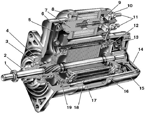
Starter 29.3708 (the design of the starter 423.3708 is similar, it differs in the cylindrical collector and steel drive lever): 1 – limiting ring; 2 – drive gear; 3 – overrunning clutch roller; 4 – overrunning clutch; 5 – drive lever; 6 – drive side cover; 7 – relay anchor; 8 – relay winding; 9 – contact plate; 10 – relay cover; 11 – contact bolts; 12 – collector; 13 – brush; 14 – cover from the collector side; 15 – casing; 16 – body; 17 – starter pole; 18 – anchor; 19 – leash ring.
In building 16 (see fig above) four poles 17 with excitation windings are secured, three of which are series and one is shunt. The housing 16 and covers 6 and 14 are pulled together with two bolts (in the case of starter 423.3708 – with studs). The anchor 18 is equipped with an end (cylindrical at starter 423.3708) collector 12. The rear end of the armature shaft rotates in a metal-ceramic sleeve pressed into cover 14, and the front end rotates in a sleeve pressed into the clutch housing.
Technical characteristics of starter 5712.3708
- Nominal power, kW…..1.55
- Current consumption at maximum power, A, no more than…..375
- Current consumption in the braked state, A, no more than…..700
- Current consumption at idle, without relay, A, no more than…..80
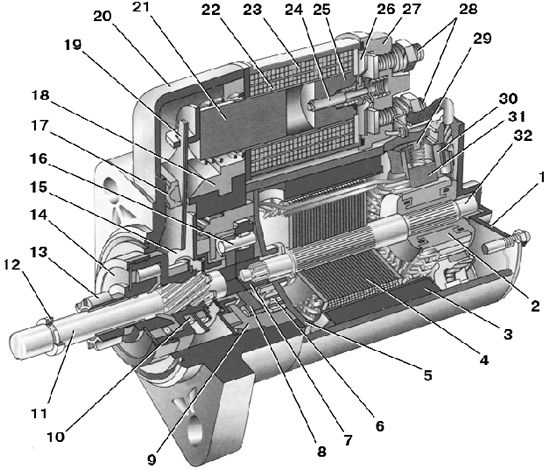
Starter 5712.3708: 1 – cover from the collector side; 2 – collector; 3 – stator pole (permanent magnet); 4 – armature core; 5 – armature shaft support; 6 – satellite; 7 - leading (central) gear; 8 – driver; 9 – solar wheel; 10 – leash ring; 11 – drive shaft; 12 – gear travel limiting ring; 13 – drive gear; 14 – overrunning clutch; 15 – drive shaft support; 16 – satellite axis; 17 – gasket; 18 – lever bracket; 19 – drive lever; 20 – drive side cover; 21 – traction relay anchor; 22 – pull-in relay winding; 23 – holding winding of the relay; 24 – traction relay rod; 25 – traction relay core; 26 – contact plate; 27 – traction relay; 28 – contact bolts; 29 – bracket; 30 – brush holder; 31 – insulated brush; 32 – anchor shaft.
Poles 3 (see Fig.) are attached to the steel housing of the starter, which are permanent magnets. The anchor shaft 32 rotates in two metal-ceramic bushings installed in the cover 1 on the collector side and in the shaft support 5. Rotation from the anchor shaft is transmitted to the drive shaft 11 through a planetary gearbox consisting of satellites 6, pinion gear 7, carrier 8 and sun wheel 9. An overrunning clutch 14 with drive gear 13 is installed on the drive shaft. A traction relay 27 is attached to the starter housing.
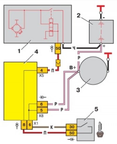
Starter wiring diagram: 1 – starter; 2 – battery; 3 – generator; 4 – mounting block; 5 – ignition switch (lock); P1 – pull-in winding of the traction relay; P2 – holding winding of the starter traction relay.
The starter connection diagram is shown in the figure above. When the starter is turned on, voltage from the battery is supplied to both windings of the starter traction relay via the ignition switch (retractor P1 and retainer P2). After the traction relay contacts are closed, the pull-in winding is switched off.