
When the key is in position "III" anti-theft device must be activated. When turning the key from position "III" into position "0" the anti-theft device should turn off. This can be checked by turning the steering wheel.
When restarting from position "I" into position "II" blocking is enabled. Key to position "II" can only be rotated from position "0".
If there are defects, replace the contact group or ignition switch.
 |  |
Key position | Live contacts | Switched circuits |
"0"-turned off | 30 and 30/1 | — |
| "I"-ignition | 30–INT | Outdoor Lighting. Instrument lighting. High beam signaling |
30/1–15/1 | The excitation winding of the generator. Ignition system. Windscreen cleaner. Carburetor idle solenoid valve control unit. Direction indicators. Reverse light. control devices | |
30/1–15/2 | Low and high beam headlights. Fog light. Headlamp cleaners. Rear window cleaner. Heated rear window. Washer. Heater fan. Engine cooling fan | |
| "II"-starter | 30–INT | See position I |
30/1–15/1 | See position I | |
30–50 | Starter | |
| "III"-parking | 30–INT | See position I |
30/1–P | parking light |
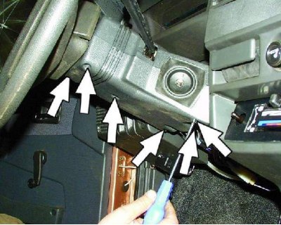
1. Remove the six screws securing the lower steering column cover.
2. Remove the lower steering column cover...
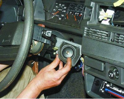
3....and the ignition lock cover.
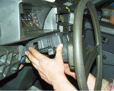
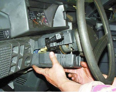
4. Remove the upper casing of the steering column.
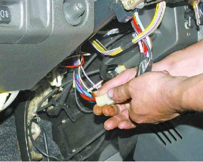
5. Disconnect the ignition switch wiring harness from the wiring harness.
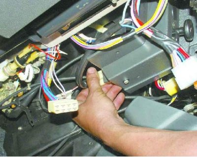
6. Disconnect the ignition switch wire harness from the ignition relay.
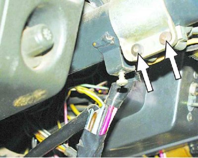
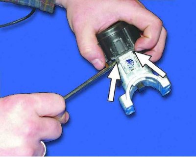
7. Insert the key into the ignition switch and turn it to the "0", to turn off the anti-theft device. Loosen the four mounting screws (two bolts are located on top of the column). Remove bracket and ignition switch (see notes 1 and 2).
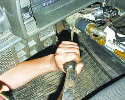
Note 1: If the bolt heads are sheared, the bolts must be drilled out or removed using a screwdriver and hammer.
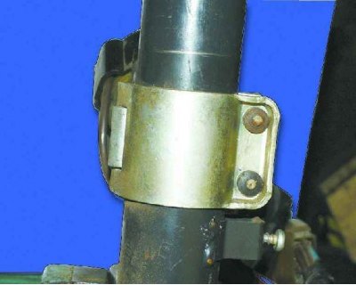
Note 2. An ignition switch is installed on some cars, fastened with two bolts. There is a slot in the top of the bracket that the hook on the ignition switch housing fits into.
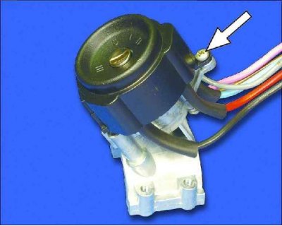
8. Loosen the screw on the switch cover.
9. Remove the switch cover by prying out the two plastic latches with a screwdriver.
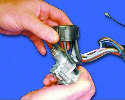
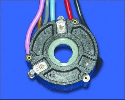
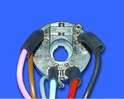
10. Remove the contact group.
11. Assembly and installation of the ignition switch is carried out in the reverse order.