




Contents: Disassembly ↓ Assembly ↓
Disassembly
If only one part needs to be replaced, you don't have to disassemble the cylinder head completely, just remove the damaged parts. Disassemble the cylinder head completely in the following order:
- install the cylinder head on a stand, unscrew the nuts and remove the carburetor with the gasket, the intake pipe and the exhaust manifold (remove the hot air intake at the same time). Remove the outlet pipe of the cooling jacket and the pipe that drains the liquid to the heater;
- unscrew the fastening nuts and remove the bearing housing together with the camshaft, seal holder and pulley. On engines 2101, 2103 remove the bearing housing with the camshaft and thrust flange;
- remove the valve levers with springs. Loosen the locknuts, unscrew the adjusting bolts and, if necessary, their bushings. Install the A.60311/R tool, compress the valve springs and release the crackers. Instead of the portable tool A.60311/R, you can also use the stationary tool 02.7823.9505;
- remove the valve springs with the plates and support washers. Turn the cylinder head and remove the valves from the bottom;
- remove the oil seals from the guide bushings.
Assembly
Before assembly, check that the retaining rings 2 (Fig. 14) of the guide bushings 3 are in place. Thoroughly clean the upper surface of the cylinder head from dirt, oil and residues of old sealant (on 2105 engines). Check that the camshaft bearing housing mounting bushings (shown by arrows on the fig. 21). Install (if they were removed) locking plates 16 lever springs and bushings 15 adjusting bolts. Tighten adjusting bolts 13 with locknuts 14.
The original can be viewed on the portal VazBook.ru
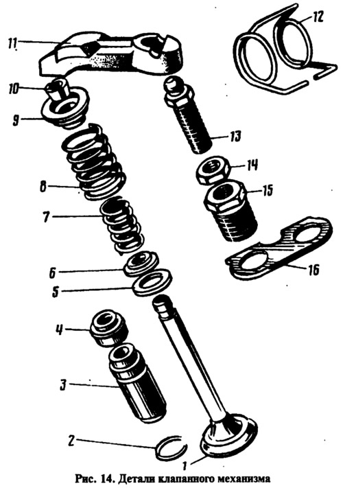
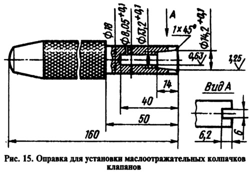
Lubricate the valves 1 and new valve stem seals 4 with engine oil (do not use old ones). Using tool 41.7853.4016 (Fig. 15), press the caps onto the valve guides. Insert the valves into the guides and then install the thrust washers 5 (see fig. 14) and 6, springs 7, 8 and plates 9. Compressing the springs with device A.60311/R, install crackers 10. Install springs 12 and valve levers 11.
On 2105 engines, assemble and install the bearing housing with the camshaft, pulley, seal holder and thrust flange in accordance with the section "Camshaft and its drive".
On engines 2101, 2103 insert the camshaft lubricated with engine oil into the bearing housing and secure it with a thrust flange. Put the sprocket on the camshaft (without securing it) and turn it until the alignment marks on the sprocket and bearing housing are aligned (see fig. 11). Remove the sprocket and, without disturbing the position of the camshaft, install the bearing housing on the cylinder head.
Check that the locating bushings fit into the bearing housing holes, and then tighten the bearing housing mounting nuts in the sequence shown on the fig. 23.
Install the cooling jacket outlet pipe and the liquid outlet pipe to the heater. Install the gasket, intake pipe and outlet manifold with hot air intake. Install the carburetor with the gasket and close it with a technological plug.