
Removing
Remove the camshaft in the following order:
- disconnect the wires from the battery;
- remove the air filter and close the carburetor neck with a technological plug;
- disconnect the carburetor throttle drive links from the intermediate lever on the cylinder head cover and the air damper cable from the carburetor;
- remove the upper protective cover of the camshaft belt drive (on engine 2105);
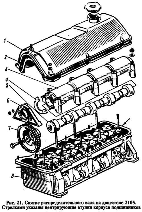
- remove cover 1 (pic. 21) cylinder heads with gasket 2;
- set the gear lever to neutral position and turn the crankshaft clockwise until the mark on the pulley is aligned (asterisk) camshaft with a mark on the bearing housing;
- on the engine 2105, remove the spring 7 (see fig. 19) tension roller 4. Loosen the bolts 3 fastening the bracket 6 of the tension roller, move it to the extreme left position and remove the belt from the camshaft pulley;
- holding pulley 7 with tool 67.7811.9509 from turning (see fig. 21) camshaft, unscrew the bolts of its fastening and remove the pulley. Instead of the named device, you can use some kind of lever with grips for the pulley holes;
- unscrew the nuts securing the bearing housing to the cylinder head 8 and remove it together with the camshaft 5;
- then, on the workbench, unscrew the nuts securing the gland holder 6, remove it and the thrust flange 4;
- Remove the camshaft from the bearing housing 3.
On engines 2101, 2103 unscrew the camshaft sprocket fastening nut, loosen nut 5 (see fig. 63) chain tensioner, press the tensioner rod with a mounting spatula and fix it with a cap nut.
- Remove the camshaft sprocket with chain and move the chain aside.
- Loosen the nuts securing the camshaft thrust flange.
- Loosen the nuts securing the bearing housing and remove it.
- Unscrew the nuts of the thrust flange, remove it and remove the camshaft from the bearing housing.
Installation
Before proceeding with the installation of the camshaft, check that the locating sleeves of the camshaft bearing housing are in place. They are put on the extreme studs of the bearing housing and in fig. 21 are shown by arrows. Clean the mating surfaces of the cylinder head from dirt, oil and old sealant residues (on engines 2105). Wrap the adjusting bolts of the valve levers deeper so that the levers are lowered and do not interfere with the installation of the bearing housing with the camshaft. Lubricate the bearing journals and camshaft cams with engine oil and insert it into the bearing housing while putting the thrust flange on the studs.
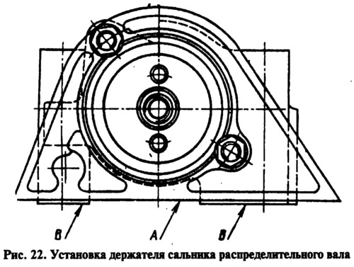
On 2105 engines, lubricate the new oil seal with engine oil and press it into the holder. Attach the holder with the stuffing box to the bearing housing without tightening the fastening nuts. Install the bearing housing on the control plate and insert the centering mandrel 67.7853.9548 into the holder in the form of a pipe with an outer diameter of 40+0,06+0,05 mm and internal 1640.02 mm. Align the holder with the stuffing box so that the non-parallelism of its lower plane A (pic. 22) relative to the lower plane B of the bearing housing was no more than 0.15 mm. Then, tightening the gland holder fastening nuts, remove the mandrel from it and attach the pulley to the camshaft, lubricating the pulley fastening bolt with KLT-75T type sealant.
Apply SUPER THREE BOHD No. 50 sealant or equivalent domestically produced KLT-75T sealant to the surface of the cylinder head mating with the gland retainer. It must be borne in mind that it is allowed to start the engine no earlier than 1 hour after applying the sealant.
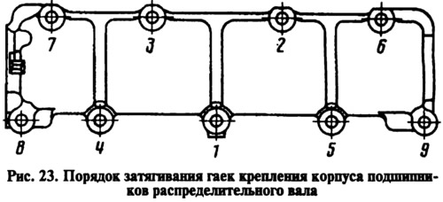
Turn the pulley until the alignment marks are aligned (see fig. eleven) and install the bearing housing with the camshaft on the cylinder head. Check whether the mounting sleeves have entered the holes of the bearing housing, and then tighten the bearing housing mounting nuts in the sequence shown in fig. 23. Holding the pulley from turning with fixture 67.7811.9509, tighten the pulley mounting bolt.
Slide the belt over the camshaft pulley and install the tensioner bracket spring. Then smoothly rotate the crankshaft two turns clockwise, keeping the belt under constant tension and not loosening it when the crankshaft stops. Tighten the tension roller bolts. After that, check the coincidence of the marks on the pulley and the camshaft bearing housing (see fig. eleven), as well as marks on the crankshaft pulley with a long mark on the camshaft drive cover (see fig. 73). If the marks do not match, then repeat the installation of the belt, and if they match, then tighten the bolts of the tension roller bracket.
On engines 2101, 2103, put an asterisk on the camshaft (without fixing it) and turn it until the alignment marks on the sprocket and bearing housing are aligned (see fig. eleven). Remove the sprocket and, without violating the position of the camshaft, install the bearing housing on the cylinder head. Check that the dowel sleeves fit into the holes in the bearing housing, and then tighten the nuts in the sequence shown in fig. 23.
Put the chain on the camshaft sprocket and install the sprocket on the camshaft. Loosen the chain tensioner cap nut by turning the crankshaft 2 turns in the direction of rotation and check that the timing marks match (see rice. eleven and rice. 73). If the marks match, tighten the tensioner cap nut, the sprocket mounting bolt, and bend the sprocket bolt lock washer.
Check and adjust the clearance between the levers and camshaft cams. Install the cylinder head cover with gasket. On 2105 engines, tighten the cap nuts in the sequence shown on rice. 13, and then install the upper camshaft belt guard.
Connect the carburetor throttle control rods to the intermediate lever on the cylinder head cover, and the choke cable to the carburetor. Adjust the carburetor throttle and choke actuators (see section «Engine settings»). Install the air filter, connect the wires to the battery, check and, if necessary, adjust the ignition timing.