Removing
On a car, this is done if it is not necessary to remove the engine itself to eliminate the malfunction, or if it is only necessary to remove carbon deposits from the surface of the combustion chamber and valves.
The sequence of operations is as follows:
- drain the coolant from the radiator and cylinder block;
- remove the air filter and close the carburetor neck with a technological plug;
- disconnect the wires from the battery, carburetor, spark plugs and from the coolant temperature gauge sensor;
- disconnect the choke cable from the carburetor;
- key 67.7812.9514 (tubular face 21 mm) turn out the spark plugs and the coolant temperature sensor;
- Disconnect the throttle actuator rods from the intermediate lever on the cylinder head cover and remove the cover;
- on the 2105 engine, first remove the top protective cover of the camshaft belt drive;
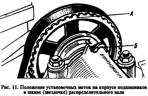
- set the gearshift lever to neutral position and turn the crankshaft clockwise until mark A is aligned (pic. eleven) on a pulley (asterisk) camshaft marked B on the bearing housing. This operation is necessary in order to correctly position the pulley when installing the cylinder head on the engine (asterisk) camshaft;
- disconnect the hoses from the carburetor, inlet pipe, from the outlet pipe of the cylinder head cooling jacket and from the fluid supply pipe to the heater;
- from the exhaust manifold, disconnect the bracket for fastening the pipe for draining fluid from the heater, the protective shield of the starter and the exhaust pipe of the mufflers.
The exhaust manifold and intake pipe are best left on the head. It is more convenient to remove them later - when disassembling the cylinder head.
On the engine 2105, remove the spring 7 (see fig. 19) tension roller 4. Loosen the bolts of the tension roller bracket, move it to the extreme left position and remove the belt from the camshaft pulley.
On engines 2101, 2103 loosen cap nut 5 (see fig. 63) chain tensioner, press the tensioner rod with a mounting spatula and fix it with a cap nut. Remove the camshaft sprocket and lower the chain down without letting it slip off the accessory drive shaft sprocket.
Turn away bolts of fastening of a head of cylinders to the block and remove a head and a lining which is between a head and the block of cylinders.
Installation
Install the cylinder head in reverse order. Before installing, check that the centering sleeves on the cylinder block are in place.
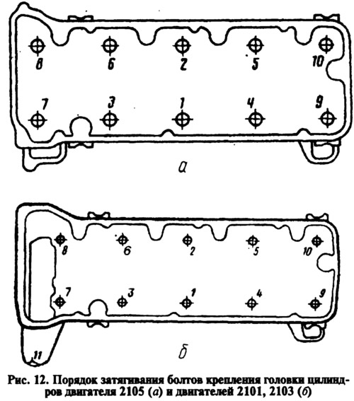
Bolts of fastening of a head of cylinders tighten in a certain sequence (pic. 12, a) in two steps: first, tighten all the bolts to a torque of 3.4–4.2 kgf·m, and then tighten them to a torque of 9.8–12.1 kgf·m. On engines 2101, 2103, then tighten the bolt 11 with a torque of 3.2-4.0 kgf·m (pic. 12b).
On 2105 engines, after putting the belt on the camshaft pulley, install the tensioner bracket spring. Then slowly rotate the crankshaft two turns clockwise, keeping the belt under constant tension and not loosening the belt when the crankshaft stops. Tighten the tension roller mounting bolts. After that, check the coincidence of the marks on the pulley and the camshaft bearing housing (see fig. eleven), as well as marks on the crankshaft pulley with a long mark on the camshaft drive cover (see fig. 73). If the marks do not match, then repeat the installation of the belt, and if they match, then tighten the bolts of the tension roller bracket.
On engines 2101, 2103, put the chain on the camshaft sprocket and install the sprocket on the camshaft. Loosen the cap nut of the chain tensioner by turning the crankshaft 2 turns in the direction of rotation and check that the timing marks match (see fig. 11 and rice. 73). If the marks match, tighten the tensioner cap nut, the sprocket mounting bolt, and bend the sprocket bolt lock washer.
After installing the cylinder head, check and adjust the ignition timing, the gap between the levers and camshaft cams, as well as the drive of the air and throttle valves of the carburetor.
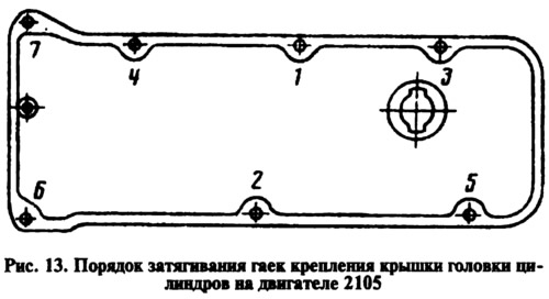
On the 2105 engine, tighten the cylinder head cover mounting nuts in the sequence shown in fig. 13.