
To prolong the service life of the crankshaft, it is possible to regrind the crankshaft journals when their surfaces are worn or damaged. By grinding, the diameters of the necks are reduced by 0.25; 0.75 and 1.00 mm.
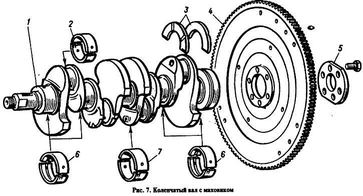
The axial movement of the crankshaft is limited by two thrust half rings 3 installed in the cylinder block on both sides of the rear main bearing. A steel-aluminum half ring is placed on the front side of the bearing, and a metal-ceramic half ring on the back side (yellow color). Semi-rings are made of normal thickness 2.31-2.36 mm and increased (repair) 2.437-2.487 mm. When assembling the engine, the half rings are selected in thickness so that the axial free play of the crankshaft is within 0.06–0.26 mm.
The crankshafts of the 2103 engine differ from the crankshafts of the 2101 and 2105 engines with a crank radius increased by 7 mm. The crankshafts of the 2103 engine have a marking on one of the cheeks of the middle main journal «2103».
Inserts of main and connecting rod bearings
All of them are thin-walled, bimetallic, steel-aluminum. Inserts 6 for the 1st, 2nd, 4th and 5th main bearings have a groove on the inner surface (since 1987 the lower shells of these bearings have been installed without a groove). Inserts 7 central (3rd) main bearings differ from other liners in the absence of a groove on the inner surface and a larger width. All shells 2 connecting rod bearings without grooves, the same and interchangeable. Repair liners are made of increased thickness under the crankshaft journals, reduced by 0.25; 0.5; 0.75 and 1 mm.
Flywheel
It is cast from cast iron and has a pressed steel ring gear for starting the engine with a starter. Flywheels 4 on all engine models are the same and interchangeable, as they are balanced separately from the crankshaft. The flywheel with the crankshaft is centered by the front bearing of the gearbox input shaft.
The flywheel is attached to the crankshaft flange with six self-locking bolts, under which one common washer 5 is placed. It is unacceptable to replace these bolts with any others. The flywheel must be installed so that the mark - conical hole A (see fig. 9) - was against the connecting rod neck of the fourth cylinder. The label is used to determine the w.m.t. in the 1st and 4th cylinders.