




Remove the plug 11 (see fig. 110) clutch release drive, and from the guide sleeve of the front cover of the gearbox, clutch 10 assembled with bearing 13 and connecting spring.
Remove the clutch housing with gasket and front gearbox cover (together with the seal and spring washer) and unscrew the reversing light switch. Then remove the speedometer drive with the gasket.
Having unscrewed the bolt of fastening of fork of shifting of III and IV gears, by moving forks engage simultaneously any two gears. This prevents turning of shafts and will allow to perform subsequent operations of disassembly.
Remove the retaining ring from the end of the secondary shaft, then, having straightened the retaining washer, unscrew the flange nut of the flexible coupling by several turns to move the centering ring, and tighten the nut again. Using the ejector A.40006/1 with the puller A.40005/4, remove the centering ring of the flexible coupling of the cardan shaft from the end of the secondary shaft, the seal of the centering ring of the flexible coupling.
Unscrew the nut and remove the flexible coupling flange using the A.40005/3/9B/9C puller, then remove the rear cover of the gearbox by unscrewing the lever lateral travel limiter screw and moving the gear shift lever to the right, releasing it from the gear engagement rods.
Remove:
- from the secondary shaft, the rear bearing and the speedometer drive pinion;
- from the reverse gear engagement rod to the fork with the spacer sleeve;
- from the axle intermediate reverse gear;
- from the intermediate shaft, the retaining ring of the reverse drive pinion, the pinion and the spring washer;
- from the secondary shaft, the retaining ring of the driven reverse gear, pressing the spring washer with the mandrel 41.7816.4069 (Fig. 117) to relieve the load from the retaining ring;
- reverse driven gear and spring washer.
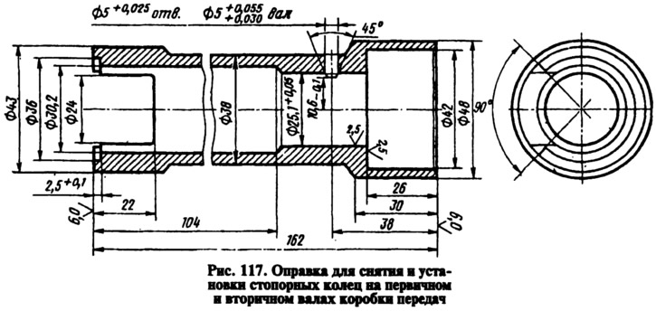
Using shaped mandrels (type of screwdrivers) and rod punches, press out the front and rear bearings of the intermediate shaft from the gearbox housing and remove the latter from the housing.
Remove the cover of the retainers, and from the crankcase - the reverse gear fork rod and the fork rod for engaging III and IV gears. Having unscrewed the bolt of the fork of shifting I and II gears, remove the rod and the fork of shifting I and II gears. While removing the rods, simultaneously remove the three locking crackers.
Remove the secondary shaft intermediate bearing lock plate and the reverse intermediate gear shaft. Use an impact drill-screwdriver to loosen the secondary shaft intermediate bearing lock plate fastening screws. Remove the primary shaft together with the bearing and synchronizer ring and remove the needle bearing from the front end of the secondary shaft.
Knock the secondary shaft out of the intermediate bearing, remove the intermediate bearing and remove the secondary shaft from the crankcase complete with gears, couplings and synchronizer rings. Then remove the III and IV gear synchronizer coupling from the shaft.
When disassembling the primary shaft, remove the retaining and blocking rings and the synchronizer spring from the rear end; after installing the shaft on the press and compressing the spring washer with the 41.7816.4069 mandrel, remove the retaining ring, then the spring washer and bearing.
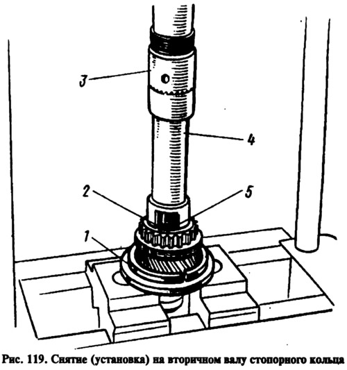
When disassembling the secondary shaft (Fig. 118), remove from the rear side of the shaft gear 22 of the 1st gear with sleeve 23, hub 16 with sliding clutch 17 for switching 1st and 2nd gears, gear 11 of the 2nd gear together with locking ring 14 of the synchronizer, install the secondary shaft with mandrel 41.7816.4069 (4 - Fig. 119) on a press, place support half rings 1 under gear 3 of the 3rd gear and, pressing with punch 3 through the mandrel on the spring washer, use pliers to remove retaining ring 5, then spring washer 2, the hub of the sliding clutch for switching 3rd and 4th gears and gear 3 of the 3rd gear.
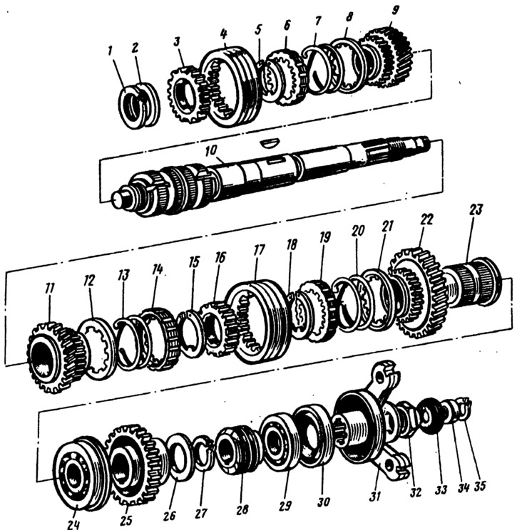
Fig. 118. Secondary shaft parts:
1, 5, 15, 18, 27, 35 - retaining rings; 2, 26 - spring washers; 3, 16 - synchronizer hubs; 4, 17 - synchronizer clutches; 6, 14, 19 - synchronizer locking rings; 7, 13, 20 - synchronizer springs; 8, 12, 21 - washers; 9, 11, 12 - gears of III, II and I gears respectively; 10 - secondary shaft; 23 - 1st gear pinion sleeve; 24, 29 - bearings; 25 - reverse gear; 28 - speedometer drive gear; 30 - oil seal; 31 - elastic coupling flange; 32 - nut; 33 - seal; 34 - centering ring.
When disassembling the gearshift lever and the rear cover, remove the cuff 19 (Fig. 120), the boot 20 of the lever, then the retaining ring 14, the washer 13, the spring 12 and the spherical washer 11. Unscrew the nuts securing the flange 16, disconnect the tension spring 3 of the lever from the eye of the bolt 1 and remove the lever together with the flange, support 10 and cup 5.
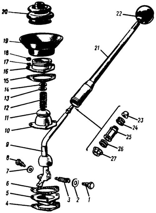
Fig. 120. Gear shift lever parts:
1 - bolt of the tension spring; 2, 7, 13 - washers; 3 - release spring; 4, 6, 15 - gaskets; 5 - guide cup; 8 - limit bolt; 9 - gear shift lever; 10 - ball joint; 11 - spherical washer; 12 - spring; 14 - retaining ring; 16 - flange; 17 - spring washer; 18 - nut; 19 - cuff; 20 - inner cover; 21 - lever rod; 22 - handle; 23 - thrust cushion; 24, 26 - elastic bushings; 25 - spacer sleeve; 27 - locking sleeve.