
On VAZ vehicles, a type 2103 clutch with a Friction lining width of 29 mm is used.
On cars VAZ-2104, VAZ-2105, a clutch with a release fork is installed, in which the fixing spring has a round section instead of the flat one used on other models. Both types of plugs are interchangeable.
The clutch is hydraulically driven. It consists of driving and driven parts. The leading part of the clutch is made in a separate unit, which is attached to the flywheel 6 (pic. 110) bolts 8. It includes: clutch cover 18, pressure plate 4 and pressure spring 2. The driven part of the clutch is the driven disk 5, located between the flywheel and the pressure plate. Two friction linings are riveted to the driven disk, and the disk itself is connected to its hub through the elements of the torsional vibration damper (damper).
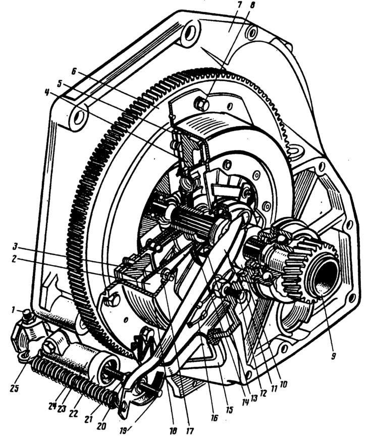
Pic. 110. Clutch:
1 - fitting for pumping; 2 - pressure spring; 3 - step rivet; 4 - pressure plate; 5 - driven disk; 6 - flywheel; 7 - clutch housing; 8 - bolt; 9 - the input shaft of the gearbox; 10 - clutch release bearing; 11 - clutch release fork; 12 - fork ball joint; 13 - clutch release bearing; 14 - thrust flange of the pressure spring; 15 - clutch release fork cover; 16 - spring; 17 - support ring of the pressure spring; 18 - clutch cover; 19 - pusher of the clutch release fork; 20 - adjusting nut; 21 - locknut; 22 - protective cap; 23 - clutch drive cylinder (worker); 24 - retraction spring of the fork; 25 - spring bracket.
The hydraulic drive consists of a pedal 15 (pic. 111), main 7 and working 70 (pic. 112) cylinders and pipelines. Drive units and parts are unified with other car models.
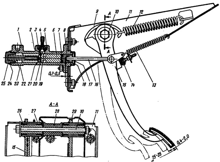
Pic. 111. Pedal and clutch master cylinder:
1 - main cylinder body; 2 - compensation hole; 3 - fitting gasket; 4 - fitting; 5 - lock spring washer; 6 - piston of the main cylinder; 7 - sealing ring; 8 - pusher piston; 9 - hook; 10 - axis of the clutch and brake pedals; I - bracket for clutch and brake pedals; 12 - clutch pedal reinforcing spring (servo spring); 13 - release spring of the clutch pedal; 14 - clutch pedal stroke limiter; 15 - clutch pedal; 16 - pusher; 17 - protective cap; 18 - retaining ring; 19 - bypass hole; 20 - sealing ring; 21 - piston bypass hole; 22 - working cavity of the cylinder; 23 - spring: 24 - gasket; 25 - cork; 26 - inner sleeve of the pedal; 27 - outer pedal sleeve; 28 - spacer sleeve; 29 - brake pedal.
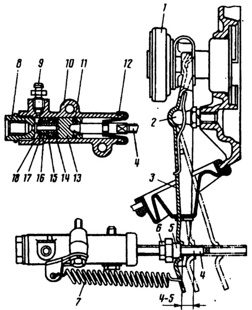
Pic. 112. Slave cylinder and clutch release fork:
1 - clutch release bearing; 2 - ball bearing; 3 - clutch release fork; 4 - pusher; 5 - adjusting nut; 6 - locknut; 7 - withdrawal spring; 8 - body plug; 9 - fitting for pumping; 10 - cylinder body; 77 - sealing ring; 12 - protective cap; 13 - piston; 14 - sealant; 15 - plate; 16 - spring; 77 - support washer; 18 - retaining ring.