
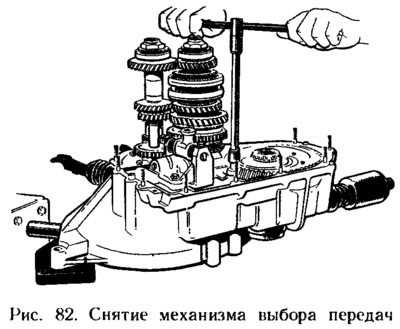
Having unscrewed the bolts for fastening the forks on the gearshift rods, remove the rods and forks. Take out the axle and remove the intermediate reverse gear. Loosen the gear selector bolts (pic. 82), take it off.
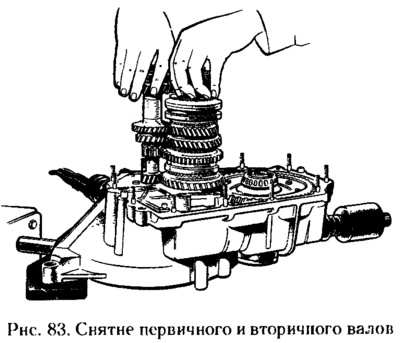
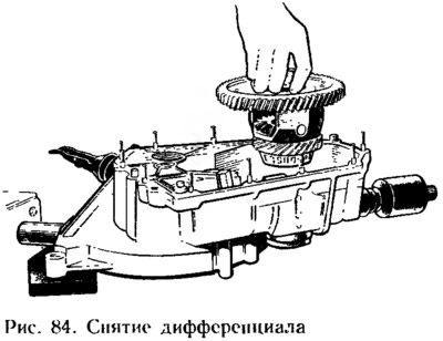
Remove the primary and secondary shafts at the same time (pic. 83) from the roller bearings of the clutch housing, and then remove the differential (pic. 84). If necessary, press out the outer rings of the shaft and differential bearings from the clutch and gearbox housings using mandrels 67.7853.9529/11 and 67.7853.95952. When pressing out the outer ring of the bearing of the secondary shaft, the oil sump 6 (see fig. 77) is destroyed.
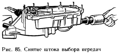
Unscrew lever 5 (see fig. 78) gear selection from rod 6 and remove the rod from the clutch housing (pic. 85). Unnecessarily, the lever and hinge are not removed from the gear selection rod, since they are installed on a special glue TB-1324.
If it is necessary to disassemble the output shaft, clamp it in a vice with pads of soft material, caulk it, and then unscrew the nut and press the bearing off the shaft with a universal puller. Then the driven gears of IV, III, II and I gears and synchronizer parts are removed from the secondary shaft in the order indicated in Fig. 86.
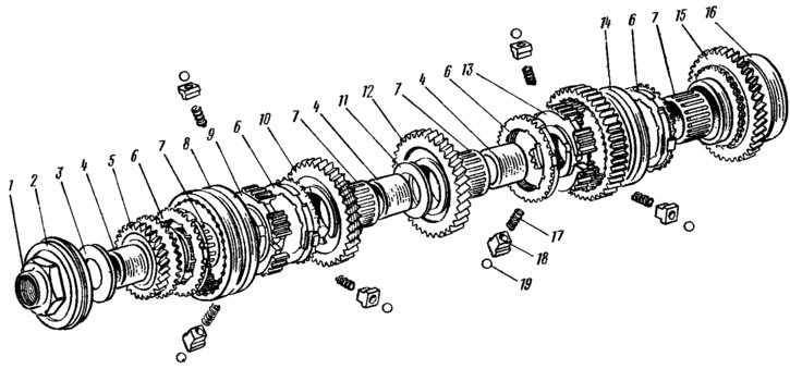
Pic. 86. Details of the secondary shaft: 1 - nut; 2 - ball bearing; 3 - thrust washer; 4 - bearing sleeve; 5 - gear IV gear; 6 — a blocking ring of the synchronizer; 7— needle bearing; 8 - synchronizer clutch III and IV gears; 9 - hub clutch synchronizer III and IV gears; 10 - gear III gear; II - thrust ring of gears; 12 — a gear wheel of the II transfer; 13 synchronizer hub of I and II gears; 14 - synchronizer clutch of I and II gears; 15 - gear wheel of the 1st gear; 16 - roller bearing; 17 - retainer spring; 18 - cracker; 19 retainer.
The hubs of the synchronizer couplings are removed with a puller A.40005/1/6.
Disassemble the differential, for which:
- if it is necessary to replace the driven gear, unscrew the bolts of its fastening and remove the gear 2 (pic. 87) from the differential box;
- remove side gears 4 with washers 5 and satellites 10 from the differential box;
- if necessary, press the bearings 9 from the differential box using the stop 67.7853.9582 and a universal puller. The differential bearing on the side of the drive gear of the speedometer drive is pressed after removing gear 7 with a special device that allows you to press the fixing antennae of the gear until they exit the annular groove of the differential box.
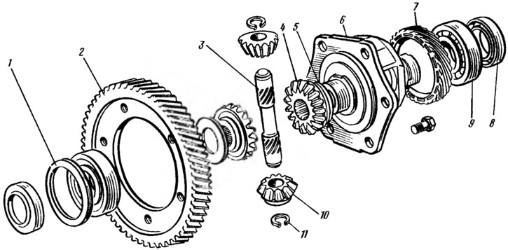
Pic. 87. Differential details: 1 - adjusting ring of differential bearings; 2 - driven gear of the main gear; 3 - axis of satellites, 4 - side gear; 5 support washer; 6 - differential box; 7 — a driving gear wheel of a drive of a speedometer; 8 - stuffing box; 9 - differential bearing; 10 - satellite; 11 - retaining ring.
If necessary, then disassemble the gear selection mechanism, for which they unscrew the axle bolt 1 (pic. 88) lever 3 and remove the axle from the housing 7 of the gear selection mechanism. In this case, the upper spring 5 of the lever, the thrust washer 4 and the gear selector lever 3 with the lower spring 2 are removed from the axle (galvanizing), and the top is uncoated.
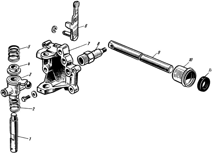
Pic. 88. Details of gear selection mechanism: 1 — an axis of the lever of a choice of transfers; 2 - lower spring; 3 - gear selection lever; 4 - thrust washer of the spring; 5 - upper spring; 6 — a fork of inclusion of a backing; 7 - housing of the gear selection mechanism; 8 — the lever of a stock of a choice of transfers; 9 — a stock of a choice of transfers; 10 - stuffing box holder; 11 - stuffing box.
Remove the retaining ring and remove the axle with the reverse fork 6 from the housing. If necessary, remove the speedometer drive, for which they unscrew the nut of its fastening and, holding the driven gear shaft, remove the speedometer drive.
Notes
1. Cylindrical mandrel, the punch of which has two belts with a diameter of 25 and 29 mm.
2. Mandrel with a diameter of 25 mm, the punch of which is rectangular in size 12 by 55 mm.