
Attention! Before removing, clean the gearbox from dirt. We install the dismantled gearbox on a workbench.
key «on 10» we unscrew the bolt securing the locking plate of the adjusting nut of the right bearing of the differential box..
... and remove the plate.
Similarly, remove the lock plate of the adjusting nut of the left bearing.
With a center punch we mark the location of the bearing caps of the differential box on the gearbox housing.
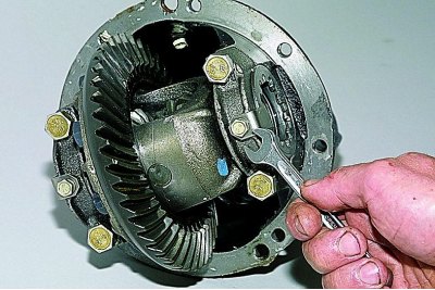
ring wrench «at 17» unscrew the two bolts securing the cover of the right bearing of the differential box..
... and take out the bolts.
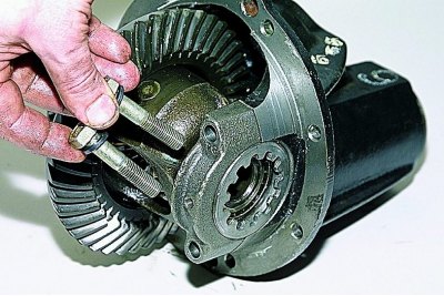
Remove the right bearing cover.
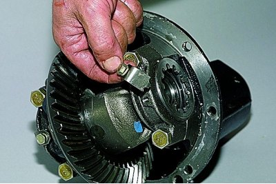
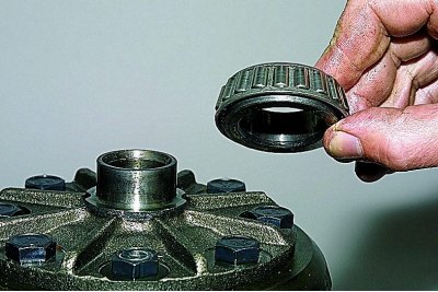
Remove adjusting nut..
... and remove the outer ring of the differential box bearing.
Similarly, remove the cover, remove the adjusting nut and remove the outer ring of the left bearing of the differential box.
If we do not change the bearings of the differential box, then we mark their outer rings in order not to confuse them during assembly.
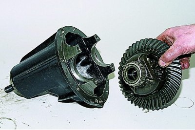
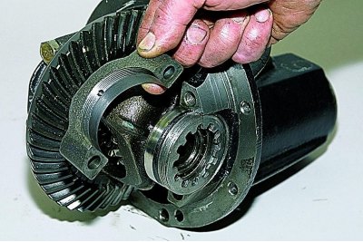
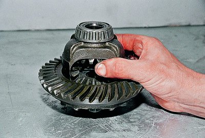
We remove the differential box assembly with the driven gear of the final drive, inner rings, separators and bearing rollers.
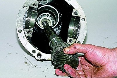
We take out the drive gear assembly with the adjusting ring, the inner ring, the separator and the rear bearing rollers and the spacer sleeve from the gearbox housing.
Remove the spacer bushing.
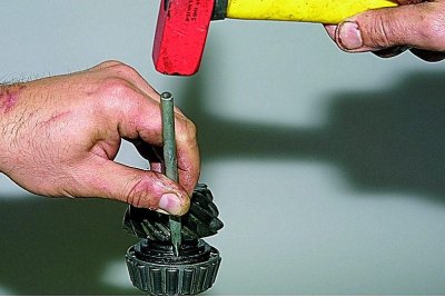
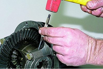
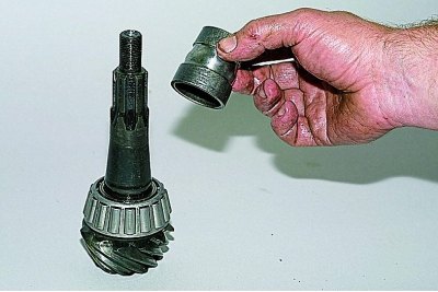
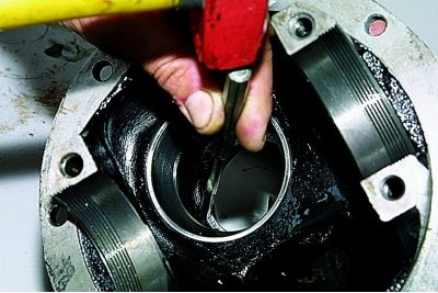
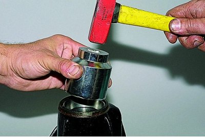
By striking with a hammer through a drift on the inner ring of the rear bearing of the gearbox,..
... remove the inner ring with a separator and rollers.
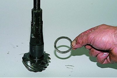
Remove the drive gear adjusting ring.
We remove the oil seal from the socket of the crankcase of the gearbox (see Replacement of an epiploon of a leading gear wheel of the main transfer).
Removing the oil deflector..
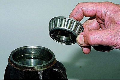
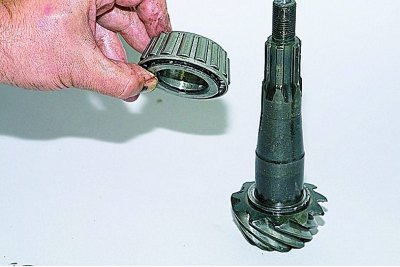
...and the inner ring of the front bearing with cage and rollers.
With a punch, we knock out the outer ring of the front bearing of the drive gear..
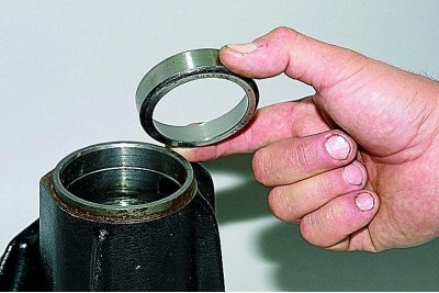
...and take it out.
Turning the crankcase over, similarly knock out the outer ring of the rear bearing of the drive gear.
To disassemble the differential..
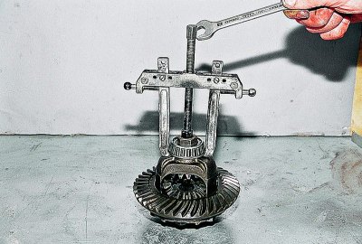
... with a puller we press the inner ring of the bearing of the differential box.
In the absence of a puller, we insert a chisel between the end face of the inner ring of the bearing and the differential box.
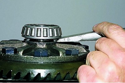
Striking the chisel, we shift the inner ring of the bearing.
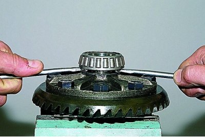
We insert two powerful screwdrivers into the resulting gap (or mounting blades) and compress..
… the bearing inner ring with cage and rollers.
Similarly, we press the inner ring of the other bearing.
Clamping the differential box in a vise with soft metal jaws,..
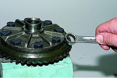
... with a spanner «at 17» unscrew the eight bolts securing the driven gear to the differential box.
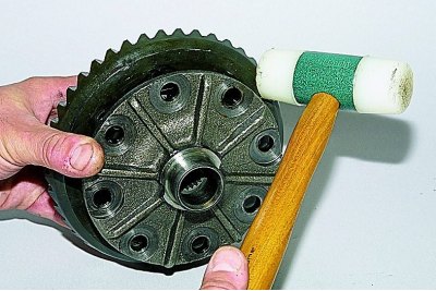
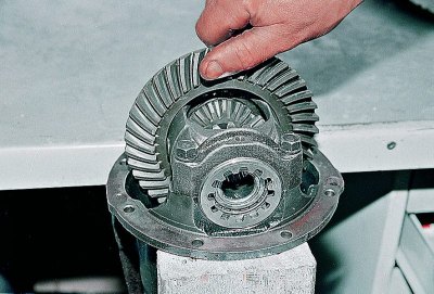
With a hammer with a plastic striker, we knock down the driven gear from the differential box..
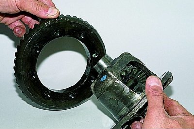
... and remove the gear.
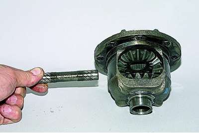
We take out the axis of the satellites.
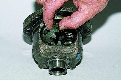
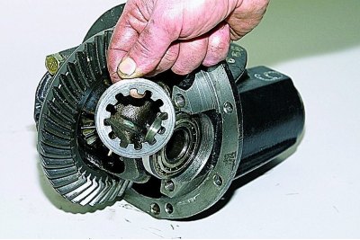
Turning the satellites, we take them out of the differential box.
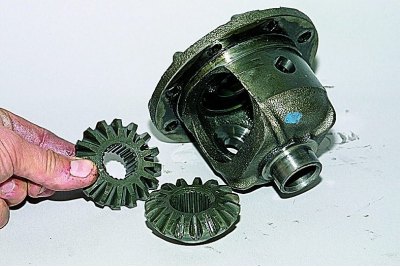
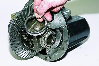
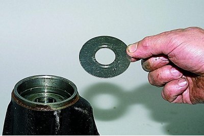
Removing the side gears...
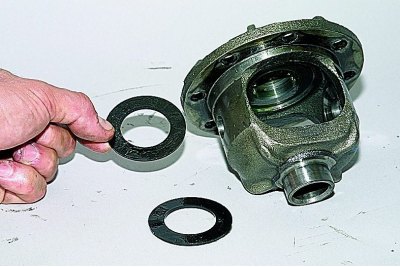
...and their support washers.
Before assembly, we wash the gearbox parts in kerosene and inspect them. Check the condition of the main gear teeth. Damage to at least one tooth (chipping, scuffing of the working surface) are not allowed. With a fine-grained sandpaper, we eliminate minor damage to the axis of the satellites, the necks of the gears of the axle shafts and their mounting holes in the differential box. In case of serious damage to parts, we replace them with new ones. If even minor damage is found to the surfaces of the bearing washers of the gears of the axle shafts, we replace the washers with new ones (with selection of washer thickness). Drive pinion and differential case bearings must be free of wear and have smooth running surfaces. Poor bearing condition causes noise and seizing gear teeth.
We press the inner rings of the bearings of the differential box with separators and rollers onto the box with a suitable piece of pipe. We fix the driven gear on the differential box.
When assembling the differential, we lubricate the gears of the axle shafts with support washers and satellites with gear oil and install them in the differential box. We turn the satellites and gears of the semi-axes so as to align the axis of rotation of the satellites with the axis of the holes in the differential box, and insert the axis of the satellites. The axial clearance of each axle gear must not exceed 0.1 mm. With an increased clearance, we replace the support washers of the gears of the semiaxes with new ones - of greater thickness. The moment of resistance to rotation of the differential gears must not exceed 14.7 Nm (1.5 kgf·m) - the gears are turned by hand.
Check the ease of rotation of the differential gears.
Suitable tool head (pipe section) Press the outer ring of the front bearing into the housing of the crankcase.
Press in the outer ring of the rear bearing in the same way.
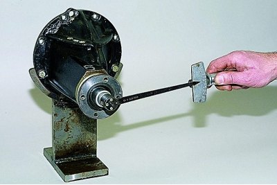
The correct position of the drive gear relative to the driven gear is ensured by selecting the thickness of the adjusting ring installed between the end of the drive gear and the inner ring of the rear bearing. When replacing the main pair of the gearbox or drive gear bearings, we select the adjusting ring. To do this, we make a fixture from an old drive gear: weld a plate 80 mm long to the gear and grind the plate to a size of 50–0.02 mm relative to the end of the gear (adjusting ring contact plane).
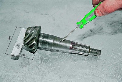
A fixture made from an old drive gear.
We grind (or finely sanded) location of the rear bearing on the pinion gear so that the inner race of the bearing has a slip fit. We install the inner ring of the rear bearing with a cage and rollers on the manufactured fixture and insert the fixture into the crankcase. Then we install the inner ring of the front bearing with the cage and rollers and the drive gear flange. Turning the gear by the flange for the correct installation of the bearing rollers, tighten the flange fastening nut to a torque of 7.9–9.8 N·m (0.8–1.0 kgf·m).
We fix the crankcase on the workbench so that its attachment plane is horizontal. We install the curved ruler in the bearing bed with an edge so that the bed ruler touches along the line.
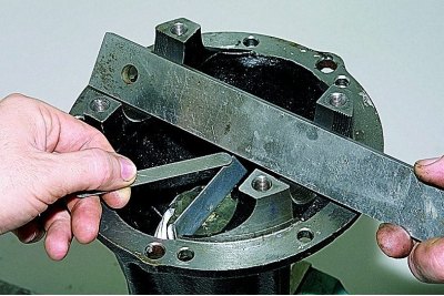
With a set of flat probes, we determine the size of the gap between the ruler and the fixture plate.
The thickness of the adjusting ring is determined by the difference between the gap and the deviation from the nominal position of the new gear (taking into account the sign of the deviation).
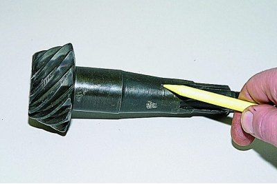
Deviation marking (in hundredths of a millimeter with signs «plus» or «minus») applied on the conical part of the gear shank.
For example, the measured clearance is 2.90 mm, and the gear is marked with a deviation from the nominal position of -15. Convert the deviation to millimeters: -15 x 0.01 = -0.15.
The required thickness of the adjusting ring will be: 2.90– (–0,15) = 3.05 mm.
We install the adjusting ring of the required thickness on the new drive gear. We remove the device from the gearbox housing and remove the inner rings of the front and rear bearings with separators and rollers.
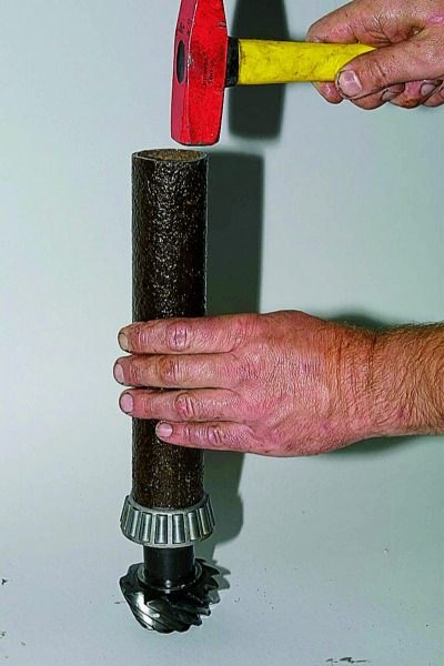
With a suitable piece of pipe, we press the inner ring of the rear bearing with a cage and rollers onto the new drive gear.
We insert the drive gear into the gearbox housing. We install a new spacer sleeve, the inner ring of the front bearing with a separator and rollers and an oil deflector. Having lubricated the working edge of the new oil seal with Litol-24 grease, we press it into the crankcase socket. Install the drive gear flange.
Having locked the flange, gradually tighten the nut of its fastening with a torque wrench until the moment of 118 N·m (12 kgf·m).
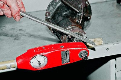
The preload of the drive gear bearings is controlled by a dynamometer,...
... periodically checking the moment of resistance of the bearings to the rotation of the drive gear.
If the moment of resistance to rotation is less than 157 N.cm (16 kgf.cm) - for new bearings, and for bearings after 30 km of run - less than 39.2 N.cm (4 kgf.cm), then we tighten the flange fastening nut, without exceeding the tightening torque. After that, we again check the moment of resistance to rotation of the drive gear.
If the moment of resistance turned out to be more than 197 N.cm (20 kgf.cm) - for new bearings, and for used bearings - more than 59.0 N.cm (6 kgf.cm), the bearing preload is exceeded.
In this case, it is necessary to replace the excessively deformed spacer sleeve with a new one and reassemble and adjust.
We install the differential assembly with bearings and adjusting nuts in the gearbox housing so that they come into contact with the outer rings of the bearings. Tighten the bearing cap bolts to the required torque.
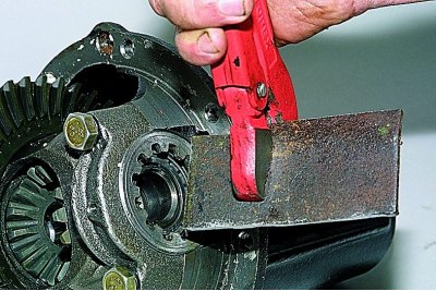
From a steel plate 49.5 mm wide and 3–4 mm thick, we make a special wrench for tightening the adjusting nuts.
The adjustment of the side clearance in the engagement of the gears of the main gear and the preload of the bearings of the differential box are carried out simultaneously, in several stages.
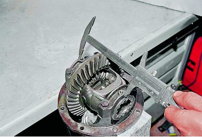
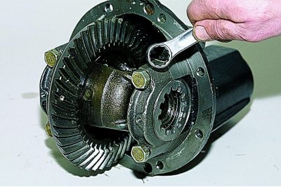
Measure the distance between the bearing caps with a caliper.
Tighten the left adjusting nut (driven gear side) until the clearance in the main gear meshing is completely eliminated.
We wrap the right nut until it stops and tighten it by 1-2 teeth of the nut.
Tightening the left nut, we set the required side clearance of 0.08–0.13 mm in the meshing of the final drive gears.
With this gap, shaking the driven gear, with the fingers of the hand we feel the minimum backlash in the engagement of the gears, accompanied by a slight knock of tooth on tooth.
When tightening the bearing cap nuts, the differential boxes diverge and the distance between them increases.
To set the preload of the bearings of the differential box, sequentially and evenly tighten both adjusting nuts of the bearings until the distance between the covers is 0.15–0.20 mm. Having set the preload of the bearings, we finally check the side clearance in the meshing of the main gear gears, which should not change. For this,…
... slowly turning the driven gear three turns, with our fingers we control the play in the engagement of each pair of teeth.
If the engagement gap is greater than the required (0.08-0.13mm) , then by rotating the adjusting nuts we bring the driven gear closer to the drive gear or move it away if the gap is smaller. In order to maintain the set bearing preload at the same time, we move the driven gear by tightening one of the adjusting nuts and loosening the other by the same angle.
After adjustment, install the locking plates of the adjusting nuts and fix them with bolts.