
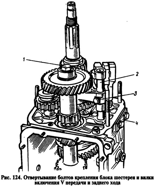
Loosen the nuts securing the rear cover 24 (see fig. 122) and take it off. One of the cover fastening nuts is unscrewed from the inside of the gearbox housing with the bottom cover removed. When removing the rear cover, it must be fed not only back, but also rotated to prevent it from touching the reverse gear and V gears. After removing the inner ring of the rear bearing 12 and the drive gear of the speedometer drive from the secondary shaft, loosen the cover fastening bolts 4 (pic. 124) clamps and unscrew bolts 1 and 3 fastening the gear unit and the fork for engaging the V gear and reverse gear.
Remove oil deflector 9 (see fig. 122), and then the sleeve 10 of the V gear and remove the rod 2 (see fig. 124) from a fork. In this case, the remote sleeve is removed from the stem. Then remove the gear assembly from the intermediate shaft spline.
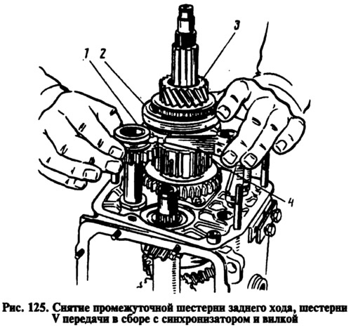
Remove intermediate gear 1 at the same time (pic. 125) reverse gear from the axle, gear 3 complete with clutch 2 and fork 4 from the secondary shaft. Remove the washer 5 from the secondary shaft (see fig. 122) and using figured mandrels such as screwdrivers, remove the hub 3 of the synchronizer of the V transmission and the driven gear 2 of the reverse gear from the key.
Carry out further disassembly of the gearbox in the order described for the four-speed gearbox.
If necessary, disassemble the lever and the gear selection mechanism, for which:
- remove protective cover 10 (see fig. 123) from flange 11, retaining and thrust rings 8 and 7, spring 6 and spherical washer 5 from the gear lever;
- mark the location of the parts relative to the mark A, printed on the guide plate, so that when assembling, connect the parts in the same position;
- having unscrewed the nuts from the fastening bolts, separate the parts of the gear selection mechanism and remove the lever 9, its ball joint 4 and rubber sealing rings 15.