
Diagram of the camshaft drive mechanism
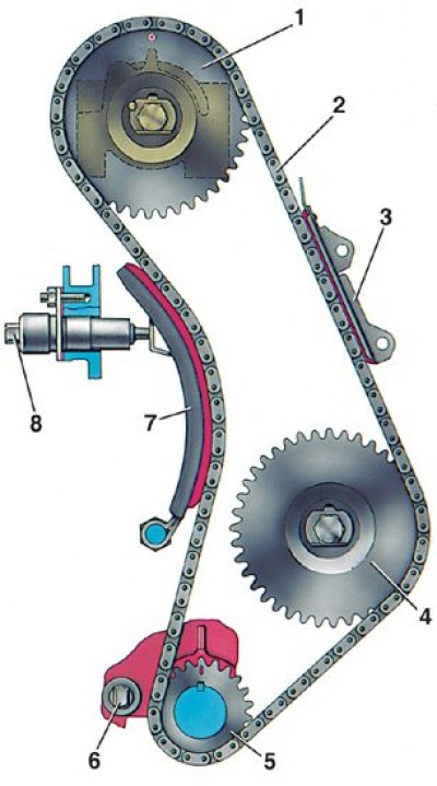
1 - camshaft sprocket; 2 - chain; 3 - chain damper; 4 - an asterisk of the oil pump drive shaft; 5 - crankshaft sprocket; 6 - restrictive finger; 7 - tensioner shoe; 8 - chain tensioner
Chain tensioner section
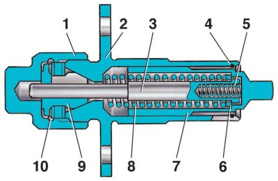
1 - cap nut; 2 - tensioner housing; 3 - rod; 4 - spring ring; 5 - plunger spring; 6 - washer; 7 - plunger; 8 - spring; 9 - cracker; 10 - spring ring
Tool 67.7824.9521 for checking wear (hoods) chains
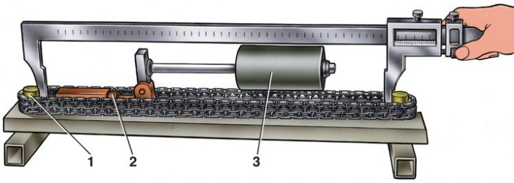
1 - roller; 2 - adjusting nut; 3 - counterweight
Camshaft drive chain (see fig. Diagram of the camshaft drive mechanism) with semi-automatic tensioner 8.
1. To adjust the chain tension, loosen the cap nut 1 (see fig. Chain tensioner section) and turn the crankshaft 1-1.5 turns in the direction of rotation. In this case, the tensioner spring 8, acting on the shoe, will automatically adjust the chain tension.
2. Then tighten the tensioner nut 1.
3. To disassemble the chain tensioner, remove the cap nut 1, clamping cracker 9 and spring ring 4, then remove plunger 7, spring 5 and rod 3 together with spring 8 and washer 6.
4. After disassembly, they check if there are any scratches on the crackers 9 and on the rod 3, and on the mating surfaces of the shoe and the plunger of the chain tensioner there are deep scratches. Replace damaged parts.
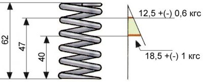
5. The elasticity of the spring 8 of the tensioner must be within the limits indicated in the figure. Worn out tensioner shoe and chain guide are replaced with new ones.
6. The chain is first washed in kerosene, and then the condition of its links is checked. On rollers and cheeks, chips, cracks and other damage are not allowed. When the engine is running, the chain stretches. It is considered operational if the tensioner provides its tension, i.e. if the chain is extended by no more than 4 mm.
7. Check the chain extractor on tool 67.7824.9521 (see fig. Tool 67.7824.9521 for checking wear (hoods) chains), having two stepped rollers 1, on which the chain is put on. With the help of counterweight 3, the chain is stretched with a force of 294 N (30 kgf) or 147 N (15 kgf). The adjusting nut 2 ensures that the axis of the counterweight is parallel to the base of the device.
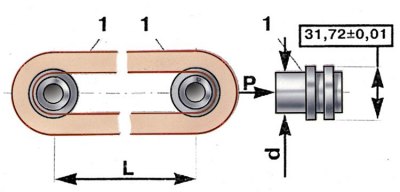
8. Stretch the chain with a force of 294 N (30 kgf), placing the counterweight in the extreme right position, then reduce the force by 147 N (15 kgf), by moving the counterweight to the extreme left position.
9. Repeat both operations again and determine the chain extension by the distance L between the axes of the rollers 1. By measuring the distance between the diameters d of the rollers with a vernier caliper and adding the diameter d to it, get the distance L between the axes of the rollers.
10. For a new chain, the distance L between the axes of the rollers is 485.755+0,5-0,1 mm for engine 2101 and 495.3+0,5-0,1 mm for engine 2103.
11. If the chain has stretched to 490 mm on the 2101 engine or to 499.5 mm on the 2103 engine, then it should be replaced.
12. Lubricate the chain with engine oil before installing on the engine.