




Camshaft drive. It is carried out from the drive sprocket 5 (Fig. 2-55) of the crankshaft by a double-row roller chain 2. The same chain also drives the sprocket 4 of the oil pump drive shaft. The chain drive has a semi-automatic tensioner 8 with a shoe 7 and a chain damper 3 with rubber pads.
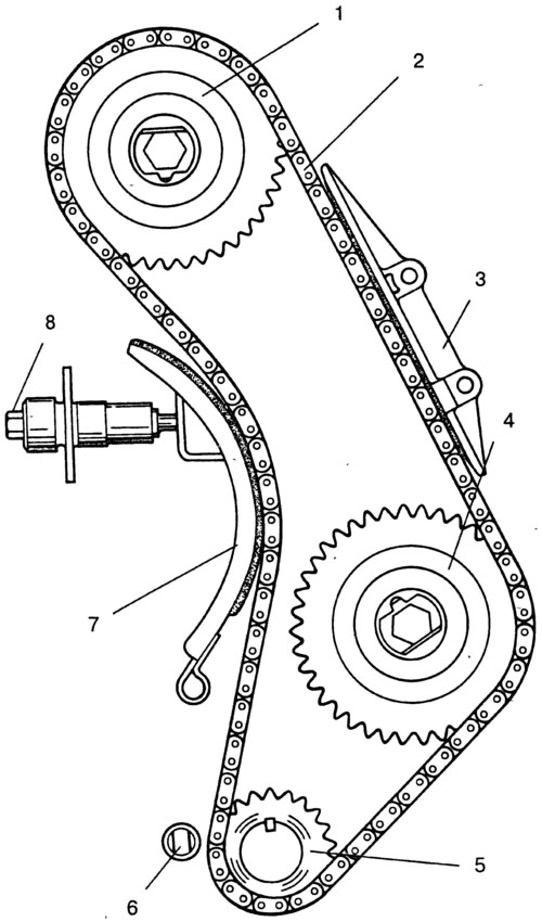
Fig. 2-55. Camshaft and auxiliary drive diagram:
1 - camshaft sprocket; 2 - chain; 3 - chain tensioner; 4 - oil pump drive shaft sprocket; 6 - limiting finger; 7 - tensioner shoe; 8 - chain tensioner.
A limiting pin 6 is installed at the bottom of the cylinder block, preventing the chain from falling into the crankcase when the camshaft sprocket 1 is removed from the vehicle.
[The information is published on the website: VAZBOOK.ru]