




Carburetor idle speed adjustment screws 2105-1107010
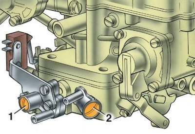
1 – mixture quantity screw; 2 – mixture quality screw
Installing limiting bushings on the idle speed adjustment screws of the carburetor 2105-107010
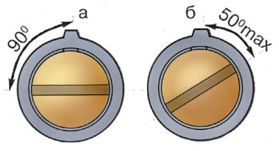
a – on the screw for the amount of mixture; b - on the mixture quality screw
The engine idle speed adjustment elements include screw 2, which determines the mixture composition, and screw 1, which regulates the amount of mixture.
To prevent the owner from violating the factory settings, the screws are fitted with plastic stop bushings that allow the screws to be turned only half a turn.
If you cannot adjust the CO content in the exhaust gases with the bushings, then, when unscrewing the screws, break the heads of the bushings, unscrew the screws, remove the bushings from them and screw the screws back into the carburetor.
Attention! The bushings installed at the factory are blue, and at service stations they are red.
Idle speed adjustment is carried out on a warmed-up engine (coolant temperature 90–95°C and oil 75–90°C) with adjusted valve timing clearances and a correctly adjusted ignition timing angle.
1. Screw 1 (see fig. Carburetor idle speed adjustment screws 2105-1107010) set the crankshaft speed to 820–900 min⁻¹ using the stand tachometer.
2. Use screw 2 to achieve a CO concentration* in the exhaust gases within 0.5–1.2% with screw 1 in this position.
3. Using screw 1, restore the crankshaft speed to 820–900 min⁻¹.
4. If necessary, use screw 2 to restore the CO concentration to 0.5–1.2%.
5. Press the plastic limiting bushings onto the screws, aligning the splines of the bushings with the mounting protrusions (see Fig. Installing the limiting bushings on the idle adjustment screws of the 2105–1107010 carburetor).
*Reduced to 20°C and 1013 GPa (760 mm Hg.).