
Scheme of the main dosing system of the carburetor and econostat
The econostat atomizer is located in the second chamber of the carburetor. In the diagram, it is conditionally shown in the first chamber.
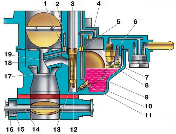
1 - emulsion jet econostat; 2 – emulsion channel of econostat; 3 - air jet of the main dosing system; 4 – econostat air jet; 5 – econostat fuel jet; 6 - needle valve; 7 - the axis of the float; 8 – a ball of a locking needle; 9 - float; 10 - float chamber; 11 - main fuel jet; 12 - emulsion well; 13 - emulsion tube; 14 - axis of the throttle valve of the first chamber; 15 - spool groove; 16 - spool; 17 - large diffuser; 18 - small diffuser; 19 - atomizer
On a VAZ-2105 car, a carburetor 2105-1107010 of an emulsion type, two-chamber, with a falling flow, is installed.
It has a balanced float chamber, two main dosing systems, an enrichment device (econostat) with a pneumatic actuator, crankcase exhaust system for the throttle valve, a pipe for supplying vacuum to the vacuum regulator of the ignition distributor, an autonomous idling system with a forced idling economizer (see fig. Installation of restrictive sleeves on the screws for adjusting the carburetor idle speed system 2105-1107010) electronically controlled by engine speed.
Scheme of the drive throttle easlonok carburetor 2105-1107010
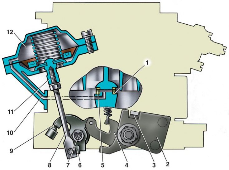
1 - pneumatic drive jet located in the diffuser of the first chamber; 2 – throttle drive lever; 3 - a lever rigidly connected to the axis of the throttle valve of the first chamber; 4 - a lever that limits the opening of the throttle valve of the second chamber; 5 - pneumatic drive jet located in the diffuser of the second chamber; 6 - lever connected to lever 9 through a spring; 7 - axis of the throttle valve of the second chamber; 8 – pneumatic actuator rod; 9 - throttle control lever of the second chamber; 10 - channel for supplying vacuum to the pneumatic actuator; 11 - stem bushing; 12 - pneumatic throttle valve of the second chamber
Carburetor starter diagram 2105-1107010
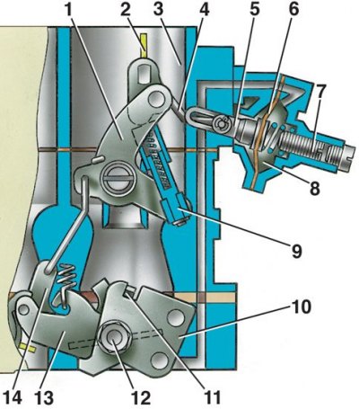
1 – air damper control lever; 2 - air damper; 3 - air pipe of the first chamber; 4 - thrust; 5 - the rod of the starting device; 6 - diaphragm; 7 - adjusting screw; 8 - cavity communicating with the throttle space; 9 - telescopic rod; 10 - throttle actuator lever; 11 - sector (tendril); 12 - axis of the throttle valve of the first chamber; 13 - lever on the axis of the throttle valve of the first chamber; 14 - lever associated with the air damper
Carburetor accelerator pump diagram 2105-1107010
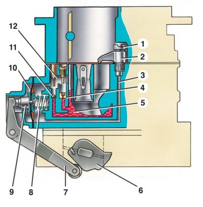
1 - screw valve; 2 - spray; 3 - fuel channel; 4 - bypass jet; 5 - float chamber; 6 - drive sector of the accelerating pump; 7 – drive lever; 8 - return spring; 9 - diaphragm cup; 10 - pump diaphragm; 11 - inlet ball valve; 12 - pump vapor chamber
The throttle valve of the second chamber has a pneumatic drive, the air valve has a diaphragm starter for starting a cold engine. Accelerator pump diaphragm type, mechanically driven, supplies fuel to the first chamber.
Calibration data for the carburetor are shown in the table Carburetor calibration data 2105-1107010.