




Chain tensioner
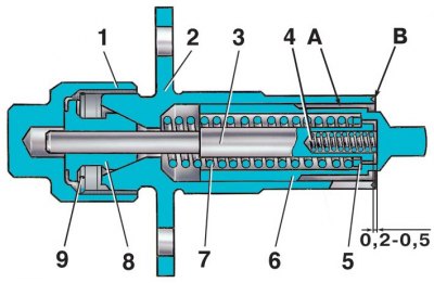
1 – cap nut; 2 – tensioner housing; 3 – rod; 4 – plunger spring; 5 – washer; 6 – plunger; 7 – spring; 8 – rusk; 9 – spring ring; A – plunger surface; B – places of kerning on the end of the body
There are differences in the cylinder head in the adjustment of clearances in the valve mechanism. The clearance of the exhaust valves on a cold engine should be within 0.18–0.22.
The chain tensioner plunger is fixed not by a locking ring, but by punching the body. Therefore, the order of its disassembly is as follows.
1. Unscrew cap nut 1, push plunger 6 in as far as possible and tighten the cap nut. Then, while pressing the plunger in, file down the edges of the housing hole at the "B" punching points and remove plunger with spring 4. Unscrew cap nut and remove rod 3 together with spring 7 and washer 5.
2. The tensioner is assembled in the reverse order of disassembly. After installing the plunger, punch the housing 2 at three points "B". In this case, the projections from punching should not touch the surface "A" when the plunger moves.