




Fuel pressure regulator operation diagram
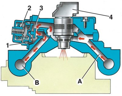
1 – pressure regulator diaphragm; 2 – spring; 3 – pressure regulator valve; 4 – nozzle; A – fuel supply channel; B – fuel drain channel
Idle speed control circuit diagram
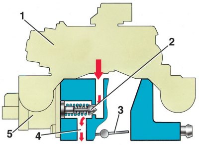
1 – fuel supply housing; 2 – idle speed control valve; 3 – throttle valve; 4 – idle channel; 5 – idle speed controller
Central fuel injection unit (see Fig. Central injection unit) is installed on the intake pipe instead of the carburetor and consists of a fuel supply housing (upper part of the unit) and throttle bodies (lower part of the unit). The fuel supply housing contains the fuel injection nozzle 2 and the fuel pressure regulator 1. The throttle valve housing contains the idle speed regulator 9, the throttle valve and the throttle valve position sensor 4. There are three pipes 6, 7 and 8 connected to the throttle valve space to select the vacuum.
The fuel pressure regulator maintains the fuel pressure supplied to the injector at a constant level within 190–210 kPa. It consists of a valve 3 (see fig. Fuel pressure regulator operation diagram) with diaphragm 1, pressed by a calibrated spring to the seat in the fuel supply housing of the unit.
When the fuel pressure becomes higher than normal, it overcomes the spring force, the valve opens, excess fuel is drained into the fuel tank through channel "B" and the drain line, and the fuel pressure decreases. When the pressure drops below normal, the valve is pressed against the seat by the spring and the fuel drain stops.
Idle speed control 5 (see fig. Idle speed controller operation diagram) regulates the crankshaft speed in idle mode, controlling the amount of air supplied bypassing the closed throttle valve through channel 4. It consists of a two-pole stepper motor and a cone valve 2 connected to it. The valve is extended or retracted by the stepper motor, according to signals from the ECU.
When the regulator needle is fully extended (which corresponds to O steps), the valve completely closes the air passage. When the needle is pushed in, the air flow is proportional to the number of steps the needle moves away from the seat.
Nozzle 4 (see fig. Fuel pressure regulator operation diagram) is an electromagnetic valve. When a voltage pulse is sent to it from the ECU, the valve opens and fuel is injected through the atomizer in a finely atomized stream under pressure into the mixing chamber above the throttle valve. After the electrical pulse ceases to be supplied, the spring-loaded valve shuts off the fuel supply.
The text is copied from the online portal: VAZBOOK
Electric fuel pump – two-stage, rotary type, non-separable, installed in the fuel tank. It provides fuel supply under pressure of more than 284 kPa. Electric fuel pump is switched on by means of auxiliary relay 21 (see subsection 12.2)
The electric fuel pump is located directly in the fuel tank, which reduces the possibility of vapor locks, since the fuel is supplied under pressure, not under vacuum.
The fuel filter is built into the feed line between the electric fuel pump and the central fuel injection unit, and is installed in the engine compartment on the left mudguard. The filter is non-separable, has a steel body with a paper filter element.
The electric intake manifold heater is installed in the lower part of the intake manifold, directly under the central fuel injection unit. It serves to accelerate the heating of the intake system of a cold engine. This ensures rapid evaporation of the fuel and its uniform distribution among the cylinders. As a result, driving performance with a cold engine is improved and the toxicity of exhaust gases is reduced.
The ECU switches on the electric heater using auxiliary relay 22 (see subsection 12.2) when all of the following conditions are met: coolant temperature is below 65°C, intake air temperature is below 80°C and supply voltage is greater than 8 V. These conditions occur with the engine cold and running with minimal electrical load from accessories.
The ECU switches off the electric heater when one of the following conditions is met: the coolant temperature is greater than or equal to 65°C, the intake air temperature is greater than 80°C and the supply voltage is less than 6 V. These conditions occur with a warm engine and/or with a high electrical load from auxiliary units.